Hardware options installation 38
13.
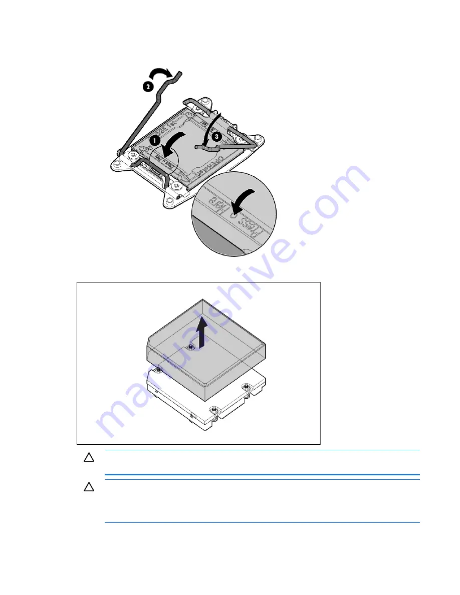
Press and hold the processor retaining bracket in place, and then close each processor locking lever.
Press only in the area indicated on the processor retaining bracket.
14.
Remove the thermal interface protective cover from the heatsink.
CAUTION:
Heatsinks specified for processor 1 and 2 are not interchangeable. Be sure to note
the appropriate orientation on the heatsink label.
CAUTION:
Heatsink retaining screws should be tightened or loosened in diagonally opposite
pairs (in an "X" pattern). Do not overtighten the screws as this can damage the board, connectors,
or screws. Use the wrench supplied with the system to reduce the possibility of overtightening the
screws.
15.
Install the heatsink:
Summary of Contents for ProLiant SL250s Gen8
Page 6: ...Contents 6 Acronyms and abbreviations 112 Documentation feedback 116 Index 117 ...
Page 55: ...Hardware options installation 55 o Left node o Right node ...
Page 76: ...Cabling 76 SFF hot plug drive cage Front quick release cage Left node ...
Page 77: ...Cabling 77 Right node Rear quick release drive cage Left node ...
Page 80: ...Cabling 80 Mini SAS cabling SFF hot plug drive cage Front quick release drive cage Left node ...
Page 81: ...Cabling 81 Right node Rear quick release drive cage Left node ...
Page 82: ...Cabling 82 Right node FBWC capacitor pack cabling Left node ...
Page 83: ...Cabling 83 Right node ...
Page 110: ...Support and other resources 110 ...
Page 111: ...Support and other resources 111 ...


