


Hardware options installation 48
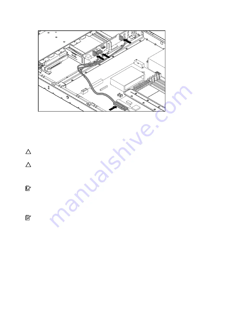
9.
Connect the HP ProLiant DL320 hot-plug SATA/SAS cable provided in the HP ProLiant DL320 hot-
plug cable option kit to the storage controller and the backplane.
10.
Install the fan assembly (on page
11.
Install the access panel.
12.
Install the server into the rack.
Battery-backed write cache battery option
CAUTION:
To prevent a server malfunction or damage to the equipment, do not add or remove the battery
pack while an array capacity expansion, RAID level migration, or stripe size migration is in progress.
CAUTION:
After the server is powered down, wait 15 seconds and then check the amber LED before
unplugging the cable from the cache module. If the amber LED blinks after 15 seconds, do not remove the
cable from the cache module. The cache module is backing up data, and data is lost if the cable is
detached.
IMPORTANT:
The battery pack might have a low charge when installed. In this case, a POST error
message is displayed when the server is powered up, indicating that the battery pack is temporarily
disabled. No action is necessary on your part. The internal circuitry automatically recharges the batteries
and enables the battery pack. This process might take up to four hours. During this time, the cache module
functions properly, but without the performance advantage of the battery pack.
NOTE:
The data protection and the time limit also apply if a power outage occurs. When power is restored
to the system, an initialization process writes the preserved data to the hard drives.
To install the BBWC battery option:
1.
Power down the server (on page
2.
Extend the server from the rack, if applicable ("
Extend the server from the rack
3.
Remove the access panel (on page
4.
Remove the BBWC battery holder (on page
5.
Insert the battery into the holder.
Summary of Contents for ProLiant DL320 Generation 5
Page 15: ...Component identification 15 Fan assembly location ...
Page 52: ...Cabling 52 Slot 1 Video connector option cable routing ...
Page 53: ...Cabling 53 Battery backed write cache cable routing ...
Page 71: ...Troubleshooting 71 ...
Page 94: ...Technical support 94 ...
Page 95: ...Technical support 95 ...


