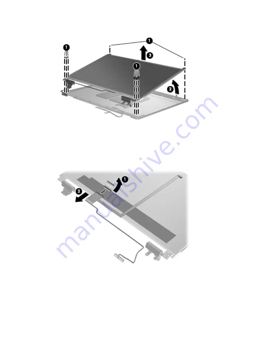
background image

11.

Lift the display panel as far as the display panel cable allows 

(3)

.

12.

Disconnect the display panel cable from the back of the display panel by lifting the tape over the
connector 

(1)

, and then disconnecting the cable from the panel 

(2)

.

The display cable is available using spare part numbers:

646969-001: HD models

646970-001: HD+ models

13.

If it is necessary to replace the display hinges, remove the four Phillips PM2.5×3.0 screws 

(1)

that secure each display hinge to the display panel.

Component replacement procedures

93

Summary of Contents for ProBook 6565b

Page 1: ...HP ProBook 6565b Notebook PC Maintenance and Service Guide ...

Page 2: ...n in the United States and or other countries SD Logo is a trademark of its proprietor The information contained herein is subject to change without notice The only warranties for HP products and services are set forth in the express warranty statements accompanying such products and services Nothing herein should be construed as constituting an additional warranty HP shall not be liable for techn...

Page 3: ...llow another hard surface such as an adjoining optional printer or a soft surface such as pillows or rugs or clothing to block airflow Also do not allow the AC adapter to contact the skin or a soft surface such as pillows or rugs or clothing during operation The computer and the AC adapter comply with the user accessible surface temperature limits defined by the International Standard for Safety o...

Page 4: ...iv Safety warning notice ...

Page 5: ...t 17 Bottom 18 3 Illustrated parts catalog 20 Service tag 20 Computer major components 21 Display components 25 Plastics Kit 27 Cable Kit 27 Mass storage devices 29 Miscellaneous parts 29 Sequential part number listing 30 4 Removal and replacement procedures 34 Preliminary replacement requirements 34 Tools required 34 Service considerations 34 Plastic parts 34 Cables and connectors 35 v ...

Page 6: ...ard drive 52 RTC battery 54 Memory modules 55 WWAN module 57 WLAN module 59 Bluetooth module 62 Modem module 63 Fan 65 Heat sink 66 Processor 69 Keyboard 71 Bottom cover 73 Speaker assembly 78 RJ 11 jack cable 80 Function board 82 System board 83 USB board 87 Display assembly and components whole hinge up cable antennas hinges enclosure 89 5 Computer Setup BIOS and System Diagnostics 98 Using Comp...

Page 7: ...tion in Device Manager 110 7 Backup and recovery 111 Windows 7 111 Backing up your information 111 Performing a system recovery 112 Using the Windows recovery tools 113 Using f11 recovery tools 113 Using a Windows 7 operating system DVD purchased separately 114 Windows Vista 115 Backing up your information 115 Performing a recovery 116 Using the Windows recovery tools 116 Using f11 recovery tools ...

Page 8: ...viii ...

Page 9: ...sors Supports dual display ports through the dock Panel All display assemblies include 2 wireless local area network WLAN antennas 39 6 cm 15 6 in HD anti glare LED SVA 1366x768 39 6 cm 15 6 in HD anti glare LED WVA 1600x900 39 6 cm 15 6 in HD anti glare LED SVA 1366x768 with WWAN 39 6 cm 15 6 in HD anti glare LED WVA 1600x900 with WWAN 39 6 cm 15 6 in HD anti glare LED SVA 1366x768 with camera 39...

Page 10: ...ing 9 5 mm 6 35 cm 2 5 in hard drives 750 GB 7200 500 GB 7200 Supports the following solid state drives 128 GB Upgrade bay Supports No Drive option Supports the following 12 7 mm SATA optical drives DVD ROM drive DVD RW SuperMulti DL drive Blu ray ROM DVD RW SuperMulti DL drive Supports the following 9 5 mm SATA hard drive 500 GB 7200 rpm Microphone Integrated dual array microphone webcam models o...

Page 11: ...play assembly world wide 5 band in WWAN panels only Subscriber identity module SIM security customer accessible in battery bay Supports no WWAN option Supports the following WWAN modules Gobi 3000 HP un2430 EV DO HSPA Mobile Broadband Ericsson HP hs2340 HSPA Mobile Broadband Integrated personal area network PAN options by way of Bluetooth module Supports no PAN option Integrated Bluetooth 2 1 Exte...

Page 12: ... battery 6 cell 2 8 Ah 62 Wh Li ion battery 6 cell 2 55 Ah 55 Wh Li ion battery 3 cell 2 8 Ah 31 Wh Li ion battery 9 cell 73 Wh HP Ultra Capacity Extended Life Battery 9 cell 100 Wh HP Extended Life Battery 6 cell 55 WHr 2 8 Ahr HP Long Life Li ion battery available only with 3 year platinum warranty HP Fast Charge Technology Security Integrated fingerprint reader Integrated smart card reader Secu...

Page 13: ...ome Premium 64 with Microsoft Office 2010 Starter Windows 7 Home Basic 32 with Microsoft Office 2010 Starter Restore Media Windows 7 Professional 64 Windows 7 Professional 32 Windows 7 Home Basic 32 Windows 7 Home Premium 64 Windows 7 Home Premium 32 DRDVD Windows 7 available with Windows 7 Home Basic and Windows 7 Starter DRDVD Windows 7 with WinDVD available with Windows 7 Professional and Windo...

Page 14: ...Category Description Optical drive Mini PCI components WLAN WWAN SIM Modem Keyboard Bluetooth module 6 Chapter 1 Product description ...

Page 15: ...s not visible from the outside of the computer 2 WLAN antennas 2 Send and receive wireless signals to communicate with wireless local area networks WLAN 3 WWAN antennas 2 select models only Send and receive wireless signals to communicate with wireless wide area networks WWAN 4 Internal microphone s 1 or 2 depending on model Record sound 5 Webcam light select models only On The webcam is in use Di...

Page 16: ... visible from the outside of the computer For optimal transmission keep the areas immediately around the antennas free from obstructions To see wireless regulatory notices refer to the section of the Regulatory Safety and Environmental Notices that applies to your country or region These notices are located in Help and Support 8 Chapter 2 External component identification ...

Page 17: ...off button Turns the TouchPad on and off 4 TouchPad zone Moves the pointer and selects or activates items on the screen NOTE Vertical scrolling is supported on the right edge of the TouchPad 5 Left TouchPad button Functions like the left button on an external mouse 6 Right pointing stick button Can be used with the pointing stick and functions like the right button on an external mouse 7 Right Tou...

Page 18: ...s a wireless local area network WLAN device and or a Bluetooth device is on Amber All wireless devices are off 5 QuickWeb light On The computer is on Off The computer is off or in Hibernation NOTE For more information refer to the HP Quickweb software Help 6 Mute light Amber Computer sound is off Off Computer sound is on 7 Calculator light On The Windows calculator function is on Blinking The Wind...

Page 19: ...ernation press the button briefly to exit Hibernation If the computer has stopped responding and Windows shutdown procedures are ineffective press and hold the power button for at least 5 seconds to turn off the computer To learn more about your power settings Windows 7 Select Start Control Panel System and Security Power Options or Windows Vista Select Start Control Panel System and Maintenance P...

Page 20: ...he default Web browser NOTE For more information refer to the HP QuickWeb software Help If your computer does not have HP QuickWeb software the button does not perform any action or function 5 Volume mute button Mutes and restores speaker sound 6 Calculator button select models only Opens the Windows calculator function 7 Fingerprint reader select models only Allows a fingerprint logon to Windows ...

Page 21: ...tem functions when pressed in combination with a function key the num lk key or the esc key 4 Windows logo key Displays the Windows Start menu 5 Windows applications key Displays a shortcut menu for items beneath the cursor 6 Integrated numeric keypad When the keypad has been enabled the keys can be used like an external numeric keypad 7 num lk key Turns the integrated numeric keypad on and off wh...

Page 22: ...r is connected to external power and the battery is charged from 90 to 99 Blinking amber A battery that is the only available power source has reached a low battery level When the battery reaches a critical battery level the battery light begins blinking rapidly Off The battery is fully charged 5 Hard drive light Blinking turquoise The hard drive or optical drive is being accessed Amber HP 3D Driv...

Page 23: ...onents NOTE The computer fan starts up automatically to cool internal components and prevent overheating It is normal for the internal fan to cycle on and off during routine operation 5 eSATA USB 2 0 combo port Connects a high performance eSATA component such as an eSATA external hard drive or connects an optional USB device 6 External monitor port Connects an external VGA monitor or projector 7 E...

Page 24: ...Serial port Connects an optional device such as a serial modem mouse or printer 3 Power connector Connects an AC adapter 4 DisplayPort Connects an optional digital display device such as a high performance monitor or projector 16 Chapter 2 External component identification ...

Page 25: ...ional computer headset microphone stereo array microphone or monaural microphone 3 USB 2 0 ports 2 Connect optional USB devices 4 Upgrade bay optical drive shown An optical drive installed in the bay select models only reads and writes to an optical disc NOTE The upgrade bay can hold either a hard drive an optical drive or a weight saver option 5 Optical drive eject button select models only Eject...

Page 26: ...r identity module SIM The SIM slot is located inside the battery bay 5 Battery bay Holds the battery 6 Vents 3 Enable airflow to cool internal components NOTE The computer fan starts up automatically to cool internal components and prevent overheating It is normal for the internal fan to cycle on and off during routine operation 7 Speakers 2 Produce sound 8 Bluetooth compartment Contains a Bluetoo...

Page 27: ...eplace the wireless module only with a wireless module authorized for use in the computer by the governmental agency that regulates wireless devices in your country or region If you replace the module and then receive a warning message remove the module to restore computer functionality and then contact technical support through Help and Support 10 Accessory battery connector Connects an optional ...

Page 28: ...omputer Serial number s n 2 This is an alphanumeric identifier that is unique to each product Part number Product number p n 3 This number provides specific information about the product s hardware components The part number helps a service technician to determine what components and parts are needed Warranty period 4 This number describes the duration in years of the warranty period for the compu...

Page 29: ...Computer major components Computer major components 21 ...

Page 30: ...n models without WWAN 665718 001 7 Speaker assembly 641186 001 8 Processor APU AMD Quad Core A8 3510M 2 5 GHz 1 5 GHz 4 MB L2 cache 45W 653358 001 AMD Quad Core A6 3410M 2 3 GHz 1 6 GHz 4 MB L2 cache 45W 653357 001 AMD Dual Core A4 3310M 2 5 GHz 2 1 GHz 2 MB L2 cache 45W 653356 001 AMD Dual Core E2 3000M 2 4 GHz 1 8 GHz 1 MB L2 cache 35W 653351 001 9 Modem module NOTE The modem module spare part k...

Page 31: ...y Iceland India Iraq Ireland Israel Italy Ivory Coast Jamaica Japan Jordan Kazakhstan Kenya Kiribati Kuwait Kyrgyzstan Laos Latvia Lebanon Lesotho Liberia Martinique Liechtenstein Lithuania Luxembourg Macedonia Madagascar Malawi Malaysia Maldives Mali Malta Marshall Islands Mauritania Mauritius Mexico Micronesia Monaco Mongolia Montenegro Morocco Mozambique Namibia Nauru Nepal the Nether Antilles ...

Page 32: ...mibia Nauru Nepal Netherlands New Zealand Nicaragua Niger Nigeria Norway Oman Palau Panama Papua New Guinea Paraguay Peru Philippines Poland Portugal Qatar Republic of Moldova Romania Rwanda Samoa San Marino Sao Tome and Principe Saudi Arabia Senegal Serbia and Montenegro Seychelles Sierra Leone Singapore Slovakia Slovenia Solomon Islands Somalia South Africa South Korea Spain Sri Lanka Swaziland ...

Page 33: ...Display components Display components 25 ...

Page 34: ...odels with WWAN 662393 001 4 Webcam module 647599 001 Microphone module 647600 001 5 Display Cable Kit For use in models with HD displays 646969 001 For use in models with HD displays 646970 001 6 WLAN antennas Included in Cable Kit Included in Display Panel Support Kit 646968 001 657831 001 7 WWAN antennas Included in Cable Kit Included in Display Panel Support Kit 646968 001 657831 001 8 Display...

Page 35: ...Plastics Kit Item Description Spare part number Plastics Kit 646971 001 1 Bottom door 2 Optical drive protective insert 3 ExpressCard slot protective insert 4 RJ 11 cover Cable Kit Plastics Kit 27 ...

Page 36: ...Item Description Spare part number Cable Kit 646968 001 1 WWAN antennas 2 WLAN antennas 3 Power connector cable 4 Bluetooth module cable 5 RJ 11 jack cable 28 Chapter 3 Illustrated parts catalog ...

Page 37: ...scellaneous parts Description Spare part number AC adapters 90 W AC adapter 609940 001 90 W AC adapter for use in India 609947 001 Power cords For use in Argentina 490371 D01 For use in Brazil 490371 202 For use in the United States 490371 001 Rubber Kit includes rubber feet and display rubber covers 646608 001 Screw Kit 646972 001 Cradle hard drive 652688 001 Mouse optical 2 button 390632 001 HP ...

Page 38: ...minican Republic East Timor Ecuador Egypt El Salvador Equitorial Guinea Eritrea Estonia Ethiopia Fiji Finland France French Guiana Gabon Gambia Georgia Germany Ghana Gibraltar Greece Grenada Guadeloupe Guatemala Guinea Guinea Bissa Honduras Hong Kong Hungary Iceland India Ireland Italy Ivory Coast Japan Jordan Kazakhstan Kenya Kiribati Kuwait Kyrgyzstan Laos Latvia Lebanon Lesotho Liberia Liechten...

Page 39: ...ychelles Sierra Leone Singapore Slovakia Slovenia Solomon Islands Somalia South Africa South Korea Spain Sri Lanka St Kitts and Nevis St Lucia St Vincent and the Grenadines Suriname Swaziland Sweden Switzerland Syria Taiwan Tajikistan Tanzania Thailand Togo Tonga Trinidad and Tobago Tunisia Turkey Turkmenistan Tuvalu Uganda Ukraine the United Arab Emirates the United Kingdom Uruguay the United Sta...

Page 40: ...er includes rubber feet 646608 001 Rubber Kit includes rubber feet and display rubber covers 646968 001 Cable Kit see Cable Kit on page 27 for more Cable Kit spare part information 646969 001 Display Cable Kit for use in models with HD displays 646970 001 Display Cable Kit for use in models with HD displays 646971 001 Plastics Kit see Plastics Kit on page 27 for more Plastics Kit spare part inform...

Page 41: ...isplay panel 39 6 cm 15 6 in HD anti glare SVA for use in models with WWAN 662394 001 Solid state drive 128 GB 662395 001 Display panel 39 6 cm 15 6 in HD anti glare LED 664017 001 DVD ROM drive 664018 001 DVD RW and CD RW SuperMulti DL combo drive 664019 001 Blu ray ROM DVD RW SuperMulti DL Drive 665718 001 System board for use in models without WWAN includes thermal pad 670434 001 Bottom door bl...

Page 42: ...e of the considerations that you must keep in mind during disassembly and assembly procedures NOTE As you remove each subassembly from the computer place the subassembly and all accompanying screws away from the work area to prevent damage Plastic parts CAUTION Using excessive force during disassembly and reassembly can damage plastic parts Use care when handling the plastic parts Apply pressure o...

Page 43: ... inserting a hard drive shut down the computer If you are unsure whether the computer is off or in Hibernation turn the computer on and then shut it down through the operating system Before handling a drive be sure that you are discharged of static electricity While handling a drive avoid touching the connector Before removing a diskette drive or optical drive be sure that a diskette or disc is no...

Page 44: ...Keep components in their electrostatic safe containers until you are ready to install them Use nonmagnetic tools Before touching an electronic component discharge static electricity by using the guidelines described in this section Avoid touching pins leads and circuitry Handle electronic components as little as possible If you remove a component place it in an electrostatic safe container The fol...

Page 45: ...nd and that proper materials are selected to avoid static charging When grounding is not possible use an ionizer to dissipate electric charges Workstation guidelines Follow these grounding workstation guidelines Cover the workstation with approved static shielding material Use a wrist strap connected to a properly grounded work surface and use properly grounded tools and equipment Use conductive f...

Page 46: ...tween the operator and ground To be effective the conductive strips must be worn in contact with the skin The following grounding equipment is recommended to prevent electrostatic damage Antistatic tape Antistatic smocks aprons and sleeve protectors Conductive bins and other assembly or soldering aids Nonconductive foam Conductive tabletop workstations with ground cords of one megohm resistance St...

Page 47: ...ide the computer serial number and model description provided on the service tag Product name 1 This is the product name affixed to the front of the computer Serial number s n 2 This is an alphanumeric identifier that is unique to each product Part number Product number p n 3 This number provides specific information about the product s hardware components The part number helps a service technicia...

Page 48: ... bottom screws have rubber covers The screw covers are included in the Rubber Kit spare part number 646608 001 and attach to the base enclosure in the locations illustrated below 40 Chapter 4 Removal and replacement procedures ...

Page 49: ... on and then shut it down through the operating system 2 Disconnect all external devices connected to the computer 3 Disconnect the power from the computer by first unplugging the power cord from the AC outlet and then unplugging the AC adapter from the computer Remove the battery 1 Position the computer upside down on a flat surface with the battery bay toward you 2 Slide the battery release latc...

Page 50: ...er Display panels 39 6 cm 15 6 in HD anti glare LED WVA 662395 001 39 6 cm 15 6 in HD anti glare LED SVA for use in models without WWAN 646978 001 39 6 cm 15 6 in HD anti glare SVA for use in models with WWAN 662393 001 Display bezels For use in models with a webcam 660276 001 For use in models without a webcam 660277 001 Webcam module 647599 001 Microphone module 647600 001 Before removing the di...

Page 51: ...ps PM2 5 5 0 screws 2 in the bottom corners of the display bezel 4 Flex the top 1 of the bezel the inside edges of the left and right sides 2 and then the bottom 3 of the bezel until it disengages from the display enclosure 5 Remove the display bezel 4 Component replacement procedures 43 ...

Page 52: ...to replace the display panel remove the six Phillips PM2 5 5 0 screws 1 at the bottom and two Phillips PM2 5 5 0 screws 2 at the top that secure the panel to the display enclosure 8 Pivot the display panel upward until it sits at a 90 degree angle 3 9 Disconnect the display panel cable from the back of the display panel 1 10 Remove the four Phillips PM2 5 4 0 screws 2 that secure the display panel...

Page 53: ...11 Slide the display panel up and out of the hinges 3 Reverse this procedure to reassemble and install the display assembly Component replacement procedures 45 ...

Page 54: ...r is off or in Hibernation turn the computer on and then shut it down through the operating system 2 Disconnect all external devices connected to the computer 3 Disconnect the power from the computer by first unplugging the power cord from the AC outlet and then unplugging the AC adapter from the computer 4 Remove the battery see Battery on page 41 Remove the SIM 1 Press in on the SIM 1 The module...

Page 55: ... computer by first unplugging the power cord from the AC outlet and then unplugging the AC adapter from the computer 4 Remove the battery see Battery on page 41 Remove the bottom door 1 Position the computer upside down on a flat surface with the battery bay toward you 2 Slide the release latch 1 and remove the locking screw if installed 2 3 Slide the release latch 3 to disengage the door from the...

Page 56: ...ough the operating system 2 Disconnect all external devices connected to the computer 3 Disconnect the power from the computer by first unplugging the power cord from the AC outlet and then unplugging the AC adapter from the computer 4 Remove the battery see Battery on page 41 5 Remove the bottom door see Bottom door on page 47 Remove the optical drive 1 Position the computer upside down with the ...

Page 57: ...drive bracket position the optical drive with the rear toward you 6 Remove the two Phillips PM2 0 3 0 screws 1 that secure the optical drive bracket to the optical drive 7 Remove the optical drive bracket 2 Reverse this procedure to install an optical drive Component replacement procedures 49 ...

Page 58: ...e computer by first unplugging the power cord from the AC outlet and then unplugging the AC adapter from the computer 4 Remove the battery see Battery on page 41 5 Remove the bottom door see Bottom door on page 47 Remove the drive from the upgrade bay 1 Position the computer upside down with the right side toward you 2 Remove the four Phillips PM2 0 4 0 screws that secure the drive assembly into t...

Page 59: ...5 Remove the drive assembly 3 from the computer Reverse this procedure to install the drive into the upgrade bay Component replacement procedures 51 ...

Page 60: ...n shut it down through the operating system 2 Disconnect all external devices connected to the computer 3 Disconnect the power from the computer by first unplugging the power cord from the AC outlet and then unplugging the AC adapter from the computer 4 Remove the battery see Battery on page 41 5 Remove the bottom door see Bottom door on page 47 Remove the hard drive 1 Position the computer upside...

Page 61: ...d drive bracket remove the two Phillips PM3 0 5 0 hard drive bracket screws 1 from each side of the hard drive 4 total screws 6 Lift the bracket 2 straight up to remove it from the hard drive Reverse this procedure to reassemble and install the hard drive Component replacement procedures 53 ...

Page 62: ...ct the power from the computer by first unplugging the power cord from the AC outlet and then unplugging the AC adapter from the computer 4 Remove the battery see Battery on page 41 5 Remove the bottom door see Bottom door on page 47 Remove the RTC battery 1 Position the computer upside down with the front toward you 2 Remove the battery from the slot as far as the attached cable will allow 1 3 Di...

Page 63: ...mber box type the computer model information and then click Search 4 Click the link for the computer model 5 Select the operating system and then click Next 6 Under Step 2 Select a Download click the BIOS link 7 Click the link for the most recent BIOS 8 Click the Download button and then follow the on screen instructions Before removing the memory module follow these steps 1 Shut down the computer...

Page 64: ... module 2 by pulling the module away from the slot at an angle NOTE Memory modules are designed with a notch 3 to prevent incorrect insertion into the memory module slot NOTE The computer uses two memory slots The top slot houses the expansion memory module and is shown in the first image below The bottom slot houses the primary memory module and is shown in the second image below Reverse this pro...

Page 65: ...ower from the computer by first unplugging the power cord from the AC outlet and then unplugging the AC adapter from the computer 4 Remove the battery see Battery on page 41 5 Remove the SIM see SIM on page 46 6 Remove the bottom door see Bottom door on page 47 Remove the WWAN module 1 Disconnect the WWAN antenna cables 1 from the terminals on the WWAN module NOTE The red WWAN antenna cable is con...

Page 66: ...incorrect insertion Figure 4 1 Removing the WWAN module NOTE If the WWAN antennas are not connected to the terminals on the WWAN module the protective sleeves must be installed on the antenna connectors as shown in the following illustration Reverse this procedure to install the WWAN module 58 Chapter 4 Removal and replacement procedures ...

Page 67: ...gdom Uruguay the United States the US Virgin Islands Uzbekistan Vanuatu Venezuela Vietnam Yemen Zaire Zambia and Zimbabwe 593836 001 Broadcom 43224AGN 802 11a b g draft n WiFi Adapter for use in Antigua and Barbuda Aruba the Bahamas Barbados Belize Canada Guam Guinea Haiti Jamaica the Nether Antilles Puerto Rico St Kitts and Nevis St Lucia St Vincent and the Grenadines Suriname the US Virgin Islan...

Page 68: ... on page 47 Remove the WLAN module 1 Position the computer right side up with the battery bay toward you 2 Disconnect the WLAN antenna cables 1 from the terminals on the WLAN module NOTE The WLAN antenna cable labeled 1 connects to the WLAN module Main terminal labeled 1 The WLAN antenna cable labeled 2 connects to the WLAN module Aux terminal labeled 2 If the computer is equipped with an 802 11a ...

Page 69: ...th a notch 4 to prevent incorrect insertion NOTE If the WLAN antennas are not connected to the terminals on the WLAN module the protective sleeves must be installed on the antenna connectors as shown in the following illustration Reverse this procedure to install the WLAN module Component replacement procedures 61 ...

Page 70: ...ation turn the computer on and then shut it down through the operating system 2 Disconnect all external devices connected to the computer 3 Disconnect the power from the computer by first unplugging the power cord from the AC outlet and then unplugging the AC adapter from the computer 4 Remove the battery see Battery on page 41 5 Remove the bottom door see Bottom door on page 47 Remove the Bluetoo...

Page 71: ...Hibernation turn the computer on and then shut it down through the operating system 2 Disconnect all external devices connected to the computer 3 Disconnect the power from the computer by first unplugging the power cord from the AC outlet and then unplugging the AC adapter from the computer 4 Remove the battery see Battery on page 41 5 Remove the bottom door see Bottom door on page 47 Remove the m...

Page 72: ...4 Disconnect the modem module cable 3 from the modem module Reverse this procedure to install the modem module 64 Chapter 4 Removal and replacement procedures ...

Page 73: ...t unplugging the power cord from the AC outlet and then unplugging the AC adapter from the computer 4 Remove the battery see Battery on page 41 5 Remove the bottom door see Bottom door on page 47 Remove the fan 1 Position the computer upside down with the front toward you 2 Loosen the three captive Phillips screws 1 that secure the fan to the base enclosure 3 Lift the fan straight up 2 to gain acc...

Page 74: ...ds Description Spare part number Heat sink 658140 001 Before removing the heat sink follow these steps 1 Shut down the computer If you are unsure whether the computer is off or in Hibernation turn the computer on and then shut it down through the operating system 2 Disconnect all external devices connected to the computer 3 Disconnect the power from the computer by first unplugging the power cord ...

Page 75: ... board 1 3 and heat sink 2 4 each time you remove the heat sink All heat sink and processor spare part kits include thermal material In the following illustration the location denoted by callout 2 on the heat sink uses thermal grease The location denoted by callout 4 on the heat sink uses a PCH thermal pad Component replacement procedures 67 ...

Page 76: ...Reverse this procedure to install the heat sink 68 Chapter 4 Removal and replacement procedures ...

Page 77: ...computer is off or in Hibernation turn the computer on and then shut it down through the operating system 2 Disconnect all external devices connected to the computer 3 Disconnect the power from the computer by first unplugging the power cord from the AC outlet and then unplugging the AC adapter from the computer 4 Remove the battery see Battery on page 41 5 Remove the bottom door see Bottom door o...

Page 78: ...move it NOTE The gold triangle 3 on the processor must be aligned with the triangle 4 embossed on the processor slot when you install the processor Reverse this procedure to install the processor 70 Chapter 4 Removal and replacement procedures ...

Page 79: ...t down through the operating system 2 Disconnect all external devices connected to the computer 3 Disconnect the power from the computer by first unplugging the power cord from the AC outlet and then unplugging the AC adapter from the computer 4 Remove the battery see Battery on page 41 5 Remove the bottom door see Bottom door on page 47 6 Remove the fan see Fan on page 65 7 Remove the heat sink s...

Page 80: ... bay to disengage the keyboard 4 Position the computer right side up with the front toward you 5 Open the computer as far as possible 6 Open the computer as far as possible 7 Lift and rotate the keyboard upward to gain access to the cables 72 Chapter 4 Removal and replacement procedures ...

Page 81: ...ard Bottom cover NOTE The bottom covers includes rubber feet NOTE Make sure to remove the modem plug from the slot in the bottom cover if the repaired unit includes a modem Description Spare part number Bottom cover 644695 001 Top cover for use on models that include a fingerprint reader without a pointing stick 641204 001 Top cover for use on models that include a fingerprint reader and a pointin...

Page 82: ...he AC adapter from the computer 4 Remove the battery see Battery on page 41 5 Remove the following components a Bottom door see Bottom door on page 47 b Hard drive see Hard drive on page 52 c Optical drive see Optical drive on page 48 d WLAN module see WLAN module on page 59 e WWAN module see WWAN module on page 57 f Modem module see Modem module on page 63 g Fan see Fan on page 65 h Heat sink see...

Page 83: ...arge rubber screw cover 3 7 Torx T8M2 5 6 0 screws 4 4 Phillips PM2 5 3 0 screws from the battery bay 3 Remove the following screws that secure the bottom cover to the computer 1 2 Phillips PM2 5 3 0 screws from the hard drive bay 2 3 Phillips PM2 0 3 0 screws from the optical drive bay Component replacement procedures 75 ...

Page 84: ...emove the wireless cables from their routing path on the bottom cover 1 and disconnect the speaker cable from the system board 2 6 Position the computer upright with the front toward you 7 Open the computer as far as possible 76 Chapter 4 Removal and replacement procedures ...

Page 85: ...o disengage the cover from the computer 10 Remove the bottom cover from the computer Reverse this procedure to install the bottom cover NOTE When replacing the bottom cover make sure to remove the modem plug from the slot in the bottom cover if the repaired unit includes a modem Component replacement procedures 77 ...

Page 86: ...AC adapter from the computer 4 Remove the battery see Battery on page 41 5 Remove the following components a Bottom door see Bottom door on page 47 b Hard drive see Hard drive on page 52 c Optical drive see Optical drive on page 48 d WLAN module see WLAN module on page 59 e WWAN module see WWAN module on page 57 f Fan see Fan on page 65 g Heat sink see Heat sink on page 66 h Keyboard see Keyboard ...

Page 87: ...3 Remove the speaker assembly 2 from the top cover Reverse this procedure to install the speaker assembly Component replacement procedures 79 ...

Page 88: ...the AC adapter from the computer 4 Remove the battery see Battery on page 41 5 Remove the following components a Bottom door see Bottom door on page 47 b Hard drive see Hard drive on page 52 c Optical drive see Optical drive on page 48 d WLAN module see WLAN module on page 59 e WWAN module see WWAN module on page 57 f Modem module see Modem module on page 63 g Fan see Fan on page 65 h Heat sink se...

Page 89: ...1 jack cable from the clips and routing channel 2 built into the base enclosure 4 Remove the RJ 11 jack cable from the top cover Reverse this procedure to install the RJ 11 jack cable Component replacement procedures 81 ...

Page 90: ...unplugging the AC adapter from the computer 4 Remove the battery see Battery on page 41 5 Remove the following components a Bottom door see Bottom door on page 47 b Hard drive see Hard drive on page 52 c Optical drive see Optical drive on page 48 d WLAN module see WLAN module on page 59 e WWAN module see WWAN module on page 57 f Fan see Fan on page 65 g Heat sink see Heat sink on page 66 h Keyboar...

Page 91: ...n models with WWAN 658143 001 System board for use in models without WWAN 665718 001 Before removing the system board follow these steps 1 Shut down the computer If you are unsure whether the computer is off or in Hibernation turn the computer on and then shut it down through the operating system 2 Disconnect all external devices connected to the computer 3 Disconnect the power from the computer b...

Page 92: ...board be sure that the following components are removed from the defective system board and installed on the replacement system board SIM see SIM on page 46 Memory module see Memory modules on page 55 WLAN module see WLAN module on page 59 WWAN module see WWAN module on page 57 Modem module see Modem module on page 63 Processor see Processor on page 69 Remove the system board 1 Position the comput...

Page 93: ...le 5 5 Position the computer upside down with the rear toward you 6 Remove the display cable from the rubber routing path mounted on the computer 1 7 Disconnect the display cable from the system board 2 Component replacement procedures 85 ...

Page 94: ...ground 9 Lift the system board up at an angle 1 and then lift the system board up and out of the computer 2 10 Remove the system board from the chassis Reverse this procedure to install the system board NOTE Make sure you install the display cable ground with the correct system board screw when replacing the system board 86 Chapter 4 Removal and replacement procedures ...

Page 95: ...g the AC adapter from the computer 4 Remove the battery see Battery on page 41 5 Remove the following components a Bottom door see Bottom door on page 47 b Hard drive see Hard drive on page 52 c Optical drive see Optical drive on page 48 d WLAN module see WLAN module on page 59 e WWAN module see WWAN module on page 57 f Fan see Fan on page 65 g Heat sink see Heat sink on page 66 h Keyboard see Key...

Page 96: ...2 Lift the board straight up out of the computer Reverse this procedure to install the USB board 88 Chapter 4 Removal and replacement procedures ...

Page 97: ...Cable Kit For use in models with HD displays 646969 001 For use in models with HD displays 646970 001 WLAN antennas Included in Cable Kit Included in Display Panel Support Kit 646968 001 657831 001 WWAN antennas Included in Cable Kit Included in Display Panel Support Kit 646968 001 657831 001 Display enclosure Enclosure Included in Display Panel Support Kit 641202 001 657831 001 Display Panel Supp...

Page 98: ...Heat sink on page 66 h Modem module see Modem module on page 63 i Keyboard see Keyboard on page 71 j Top cover see Bottom cover on page 73 k Function board see Function board on page 82 l System board see System board on page 83 Remove the display assembly 1 Position the computer right side up with the front toward you 2 Open the computer as far as possible 3 Remove the four Phillips PM2 5 7 0 scr...

Page 99: ...splay assembly straight up and remove it CAUTION When installing the display assembly be sure that the wireless antenna cables are routed and arranged properly Failure to properly route the antennas can result in degradation of the computer s WLAN and WWAN performance Component replacement procedures 91 ...

Page 100: ...f the bezel until it disengages from the display enclosure 8 Remove the display bezel 4 Display bezels are available using the following spare part numbers 660276 001 for use in models with a webcam 660277 001 for use in models without a webcam 9 To remove the display panel remove the eight Phillips PM2 5 4 0 screws 1 that secure the display panel to the brackets 10 Rotate the top of the panel upw...

Page 101: ... tape over the connector 1 and then disconnecting the cable from the panel 2 The display cable is available using spare part numbers 646969 001 HD models 646970 001 HD models 13 If it is necessary to replace the display hinges remove the four Phillips PM2 5 3 0 screws 1 that secure each display hinge to the display panel Component replacement procedures 93 ...

Page 102: ... screws that secure the hinge covers 1 and then pull the hinges toward one another 2 to remove them Display hinge covers are available in the Display Hinge Kit spare part number 647677 001 16 If you need to remove the WLAN antennas remove the antenna cables from the clips 1 and routing paths built into the display enclosure 94 Chapter 4 Removal and replacement procedures ...

Page 103: ...move the WWAN antennas remove the antenna cables from the clips 1 and routing paths built into the display enclosure 19 Lift the antennas 2 and cables 3 straight up out of the display enclosure CAUTION When installing the display assembly be sure that the wireless antenna cables are routed and arranged properly Failure to properly route the antennas can result in degradation of the computer s WWAN...

Page 104: ... the correct locations to insert the hinges into the display enclosure Use the following image as a reference for display cable and antenna installation 1 Wireless antennas 2 Wireless antennas 3 Display cable 4 Webcam cable 96 Chapter 4 Removal and replacement procedures ...

Page 105: ...10 pieces of double sided tape are mounted on the inside of the bezel Note tape locations according to the following image Component replacement procedures 97 ...

Page 106: ... Startup Menu message is displayed at the bottom of the screen 2 Press f10 to enter Computer Setup Navigating and selecting in Computer Setup To navigate and select in Computer Setup follow these steps 1 Turn on or restart the computer and then press esc while the Press the ESC key for Startup Menu message is displayed at the bottom of the screen To select a menu or a menu item use the tab key and...

Page 107: ...uter Setup NOTE Restoring defaults will not change the hard drive mode To return all settings in Computer Setup to the values that were set at the factory follow these steps 1 Turn on or restart the computer and then press esc while the Press the ESC key for Startup Menu message is displayed at the bottom of the screen 2 Press f10 to enter Computer Setup 3 Use a pointing device or the arrow keys t...

Page 108: ...llation download and install a BIOS update only when the computer is connected to reliable external power using the AC adapter Do not download or install a BIOS update while the computer is running on battery power docked in an optional docking device or connected to an optional power source During the download and installation follow these instructions Do not disconnect power from the computer by...

Page 109: ...System Diagnostics Start up test This test analyzes the main computer components that are required to start the computer Run in test This test repeats the start up test and checks for intermittent problems that the start up test does not detect Hard disk test This test analyzes the physical condition of the hard drive and then checks all data in every sector of the hard drive If the test detects a...

Page 110: ...dc 4 74 A 90 W Operating current 4 74 A Temperature Operating 5 C to 35 C 41 F to 95 F Nonoperating 20 C to 60 C 4 F to 140 F Relative humidity noncondensing Operating 10 to 90 Nonoperating 5 to 95 Maximum altitude unpressurized Operating 15 m to 3 048 m 50 ft to 10 000 ft Nonoperating 15 m to 12 192 m 50 ft to 40 000 ft Shock Operating 125 g 2 ms half sine Nonoperating 200 g 2 ms half sine Random...

Page 111: ...ric U S Dimensions Height 21 0 cm 8 25 in Width 35 9 cm 14 15 in Diagonal 39 6 cm 15 6 in Surface treatment Anti glare Contrast ratio 300 1 typical Refresh rate 60 Hz Brightness 200 nits typical Pixel resolution Pitch 0 252 mm Format 1366 768 Configuration RGB stripe Backlight LED PPI 101 ppi Viewing angle 30 horizontal minimum 10 vertical minimum 30 30 20 10 Left Right Down Up minimum or 45 45 35...

Page 112: ... in Surface treatment Anti glare Contrast ratio 300 1 typical Refresh rate 60 Hz Brightness 200 nits typical Pixel resolution Pitch 0 2151 mm Format 1600 900 Configuration RGB stripe Backlight LED PPI 118 ppi Viewing angle 30 30 20 10 Left Right Down Up minimum or 45 45 35 25 Left Right Down Up typical 104 Chapter 6 Specifications ...

Page 113: ...l read including setting Single track 1 5 ms 3 ms 3 ms 3 ms Average 11 ms 13 ms 13 ms 13 ms Maximum 14 ms 24 ms 24 ms 24 ms Logical blocks 1 465 149 168 1 048 576 000 625 141 400 488 397 168 Disc rotational speed 7200 rpm Operating temperature 5 C to 55 C 41 F to 131 F 1 GB 1 billion bytes when referring to hard drive storage capacity Actual accessible capacity is less Actual drive specifications ...

Page 114: ... DVD R 9 DVD RW DVD RAM BD R BD RE Access time CD DVD BD ROM Random 180 ms 180 ms 230 ms Maximum Media Capacity read 50 GB Maximum Media Capacity write 8 5 GB Data transfer rate 24X CD ROM 3 600 KB sec 8X DVD 10 800 KB sec 2X BD ROM 9 000 KB sec 16X CD R 3 600 KB sec 16X CD RW 2 400 KB sec 8X DVD R 10 800 KB sec 6X DVD RW 8 100 KB sec 8X DVD R 10 800 KB sec 6X DVD RW 8 100 KB sec 4X DVD R Dual Lay...

Page 115: ...tandard disc 12 cm 4 72 in Mini disc 8 cm 3 15 in Disc thickness 1 2 mm 0 047 in Track pitch 0 74 µm Access time CD DVD Random 175 ms 230 ms Full stroke 285 ms 335 ms Audio output level Line out 0 7 Vrms Cache buffer 2 MB Data transfer rate 24X CD ROM 3 600 KB sec 8X DVD ROM 10 800 KB sec 24X CD R 3 600 KB sec 16X CD RW 2 400 KB sec 8X DVD R 10 800 KB sec 4X DVD RW 5 400 KB sec 8X DVD R 10 800 KB ...

Page 116: ...R for Dual Layer HD DVD RW CD R and CD RW DVD R DVD R 9 DVD RW DVD R DVD R 9 DVD RW DVD RAM Access time CD DVD HD Random 170 ms 170 ms 230 ms Cache buffer 8 MB Data transfer rate 24X CD ROM 3 600 KB sec 8X DVD 10 800 KB sec 24X CD R 3 600 KB sec 16X CD RW 2 400 KB sec 8X DVD R 10 800 KB sec 4X DVD RW 5 400 KB sec 8X DVD R 10 800 KB sec 4X DVD RW 5 400 KB sec 2 4X DVD R 9 2 700 KB sec 5X DVD RAM 6 ...

Page 117: ... disc 12 cm 4 72 in 8 cm 3 15 in Disc thickness 1 2 mm 0 047 in Track pitch 0 74 µm Access time CD DVD Random 100 ms 125 ms Full stroke 175 ms 225 ms Audio output level Line out 0 7 Vrms Cache buffer 512 KB Data transfer rate CD R 24X 3600 KB s 150 KB s at 1X CD rate CD RW 10X 1500 KB s 150 KB s at 1X CD rate CD ROM 24X 3600 KB s 150 KB s at 1X CD rate DVD 8X 10 800 KB s 1 352 KB s at 1X DVD rate ...

Page 118: ...oftware running utilities or changing Windows settings Refer to Windows Help and Support for more information After you open Device Manager drill down to a device and double click it to access its properties To access Device Manager in Windows 7 1 Select Start Computer System properties 2 In the left pane click Device Manager To access Device Manager in Windows Vista 1 Select Start Computer System...

Page 119: ... automatic backups select models only Creating system restore points Recovering individual files Restoring the computer to a previous state Recovering information using recovery tools NOTE For detailed instructions perform a search for these topics in Help and Support In case of system instability HP recommends that you print the recovery procedures and save them for later use NOTE Windows include...

Page 120: ...r each disc before inserting it into the external drive To create a backup using Backup and Restore NOTE Be sure that the computer is connected to AC power before you start the backup process NOTE The backup process may take over an hour depending on file size and the speed of the computer 1 Select Start All Programs Maintenance Backup and Restore 2 Follow the on screen instructions to set up your...

Page 121: ...eparately For additional information refer to Using a Windows 7 operating system DVD purchased separately on page 114 3 If the Windows partition and the HP Recovery partition are listed restart the computer and then press f8 before the Windows operating system loads 4 Select Startup Repair 5 Follow the on screen instructions NOTE For additional information on recovering information using the Windo...

Page 122: ...ents and reformats the hard drive All files you have created and any software installed on the computer are permanently removed When reformatting is complete the recovery process helps you restore the operating system as well as drivers software and utilities To initiate recovery using a Windows 7 operating system DVD NOTE This process takes several minutes 1 If possible back up all personal files...

Page 123: ...lp and Support for more information Backing up your information Recovery after a system failure is as complete as your most current backup You should create your initial backup immediately after software setup As you add new software and data files you should continue to back up your system on a regular basis to maintain a reasonably current backup You can back up your information to an optional e...

Page 124: ...ws Vista operating system DVD purchased separately on page 117 Using the Windows recovery tools To recover information you previously backed up 1 Select Start All Programs Maintenance Backup and Restore Center 2 Follow the on screen instructions to recover your entire computer select models only or your files To recover your information using Startup Repair follow these steps CAUTION Using Startup...

Page 125: ...n To find the partition select Start Computer NOTE If the HP Recovery partition has been deleted you must recover your operating system and programs using the Windows Vista operating system DVD and the Driver Recovery disc both purchased separately For additional information refer to Using a Windows Vista operating system DVD purchased separately on page 117 3 Turn on or restart the computer and t...

Page 126: ...nd then insert the Windows Vista operating system DVD into the optical drive before the Windows operating system loads 3 When prompted press any keyboard key 4 Follow the on screen instructions 5 Click Next 6 Select Repair your computer 7 Follow the on screen instructions 118 Chapter 7 Backup and recovery ...

Page 127: ...s listed below are applicable to all countries and regions The length of the power cord set must be at least 1 5 m 5 0 ft and no more than 2 0 m 6 5 ft All power cord sets must be approved by an acceptable accredited agency responsible for evaluation in the country or region where the power cord set will be used The power cord sets must have a minimum current capacity of 10 amps and a nominal volt...

Page 128: ...g must be a two pole grounding type with a NEMA 5 15P 15 A 125 V or NEMA 6 15P 15 A 250 V configuration 3 The appliance coupler flexible cord and wall plug must bear a T mark and registration number in accordance with the Japanese Dentori Law The flexible cord must be Type VCT or VCTF 3 conductor 1 00 mm conductor size The wall plug must be a two pole grounding type with a Japanese Industrial Stan...

Page 129: ...carefully NOTE Materials Disposal This HP product contains mercury in the backlight in the display assembly that might require special handling at end of life Disposal of mercury may be regulated because of environmental considerations For disposal or recycling information contact your local authorities or see the Electronic Industries Alliance EIA Web site at http www eiae org This section provid...

Page 130: ...el to the display assembly 2 Lift up and out on the left and right inside edges 1 and the top and bottom inside edges 2 of the display bezel until the bezel disengages from the display assembly 3 Remove the display bezel 3 4 Remove all screws 1 2 that secure the display panel assembly to the display enclosure 122 Chapter 9 Recycling ...

Page 131: ...losure 6 Position the display panel assembly upside down 7 Remove all screws that secure the display panel frame to the display panel 8 Use a sharp edged tool to cut the tape 1 that secures the sides of the display panel to the display panel frame Display 123 ...

Page 132: ...lay panel 10 Remove the screws 1 that secure the backlight cover to the display panel 11 Lift the top edge of the backlight cover 2 and swing it outward 12 Remove the backlight cover 13 Position the display panel right side up 124 Chapter 9 Recycling ...

Page 133: ...15 Position the display panel upside down WARNING The backlight contains mercury Exercise caution when removing and handling the backlight to avoid damaging this component and causing exposure to the mercury 16 Remove the backlight frame from the display panel Display 125 ...

Page 134: ...CD panel 19 Remove the screws 2 that secure the LCD panel to the display rear panel 20 Release the LCD panel 3 from the display rear panel 21 Release the tape 4 that secures the LCD panel to the display rear panel 22 Remove the LCD panel 23 Recycle the LCD panel and backlight 126 Chapter 9 Recycling ...

Page 135: ...umber 47 buttons calculator 12 left pointing stick button 9 left TouchPad 9 optical drive eject 17 power 11 QuickWeb 12 right pointing stick button 9 right TouchPad 9 TouchPad 11 TouchPad on off 9 volume mute 12 wireless 11 C Cable Kit contents 28 spare part number 24 28 32 cables service considerations 35 calculator button identifying 12 calculator light 10 caps lock light identifying 10 chipset ...

Page 136: ...spare part number 22 32 66 hinge removal 93 spare part number 32 HP QuickWeb light 10 I integrated numeric keypad identifying 13 integrated webcam light identifying 7 internal display switch 7 internal microphones identifying 7 J jacks audio in microphone 17 audio out headphone 17 network 17 RJ 11 modem 16 RJ 45 network 17 K keyboard product description 4 removal 71 spare part numbers 22 31 32 71 ...

Page 137: ...modem jack identifying 16 RJ 11 cover illustrated 27 RJ 11 jack cable illustrated 28 removal 80 RJ 45 network jack identifying 17 RTC battery removal 54 spare part number 24 32 54 Rubber Kit spare part number 32 rubber screw covers spare part number 40 S screw covers locations 40 spare part number 40 Screw Kit spare part number 29 32 security cable slot identifying 17 security product description ...

Page 138: ...nd Restore 111 Windows logo key identifying 13 Windows Vista operating system DVD 117 wireless antennas disconnecting 57 60 identifying 7 wireless button identifying 11 wireless lights 10 14 wireless module identifying 19 wireless product description 3 WLAN antennas illustrated 28 spare part number 26 89 WLAN antennas identifying 7 WLAN module removal 59 spare part number 59 spare part numbers 23 ...

Reviews: