


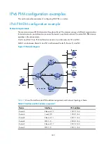


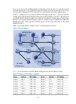


346
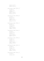
Figure 96
Network diagram
shows the interface and IPv6 address assignment, and network topology scheme.
Table 28
Interface and IPv6 address assignment
Device Interface
IPv6 address
Router A
Ethernet 1/1
1001::1/64
Router A
Serial 2/0
1002::1/64
Router A
POS 5/0
1003::1/64
Router B
Ethernet 1/1
2001::1/64
Router B
POS 5/0
2002::1/64
Router C
Ethernet 1/1
2001::2/64
Router C
POS 5/0
3001::1/64
Router D
Ethernet 1/1
4001::1/64
Router D
Serial 2/0
1002::2/64
Router D
POS 5/0
4002::1/64
Router E
POS 5/0
3001::2/64
Router E
POS 5/1
2002::2/64
Router E
POS 5/2
1003::2/64
Router E
POS 5/3
4002::2/64
Ethern
et
E
the
rn
et
Ethern
et
N1
N2
S2/0
S2/0