


89
Task
Command
Remarks
Reset PIM control message
counters.
reset pim
[
all-instance
|
vpn-instance
vpn-instance-name
]
control-message counters
[
interface
interface-type interface-number
]
Available in user
view.
PIM configuration examples
This section provides examples of configuring PIM on routers.
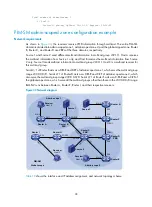
PIM-DM configuration example
Network requirements
As shown in
, the receivers receive VOD information through multicast. The receiver groups of
different organizations form stub networks, and one or more receiver hosts exist in each stub network. The
entire PIM domain operates in the dense mode.
Host A and Host C are multicast receivers in two stub networks N1 and N2.
IGMPv2 runs between Router A and N1 and between Router B, Router C, and N2.
Figure 31
Network diagram
shows the interface and IP address assignment, and network topology scheme.
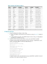
Table 8
Interface and IP address assignment
Device Interface
IP address
Router A
Ethernet 1/1
10.110.1.1/24
Router A
Serial 2/0
192.168.1.1/24
Source
10.110.5.100/24
PIM-DM
Router A
Router B
Router C
Router D
Receiver
Host A
Host B
Host C
Host D
Receiver
Eth1/1
Eth1/1
Eth1/1
Eth1/1
POS5/0
POS5/0
POS5/0
PO
S5
/1
S2/
0
S2/0