background image

Hardware Options Installation 

Installing a Hard Drive into a Removable Media Bay 

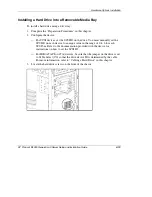
To install a hard drive using a drive tray: 

1. 

Complete the “Preparation Procedures” in this chapter. 

2. 

Configure the device: 

—  For SCSI devices, set the SCSI ID on the drive. You must manually set the 

SCSI ID on each device to a unique value in the range of 0 to 6 for each 
SCSI bus. Refer to the documentation provided with the device for 
instructions on how to set the SCSI ID. 

—  For IDE (ATAPI or ATA) devices, be sure that the jumper on the drive is set 

to Cable Select (CS) so that the drive device ID is determined by the cable. 
For more information, refer to “Cabling a Hard Drive” in this chapter. 

3. 

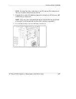
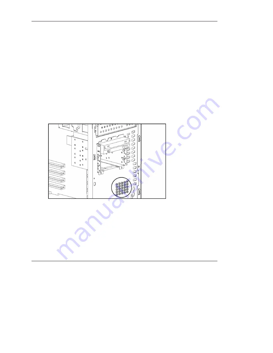
Locate the hard drive screws on the front of the chassis. 


HP ProLiant ML330 Generation 3 Server Setup and Installation Guide 

4-13


HP CONFIDENTIAL


Writer: Rob Weaver File Name: e-ch4 Hardware Options Installation.doc 

Codename: Flashback Part Number: 322383-001 Last Saved On: 2/11/03 1:24 PM 

Summary of Contents for ML330 - ProLiant - G3

Page 1: ...neration 3 Server Setup and Installation Guide April 2003 First Edition Part Number 322383 001 HP CONFIDENTIAL Writer Rob Weaver File Name a frnt doc Codename Flashback Part Number 322383 001 Last Saved On 2 11 03 1 16 PM ...

Page 2: ...is document is provided as is without warranty of any kind and is subject to change without notice The warranties for HP products are set forth in the express limited warranty statements accompanying such products Nothing herein should be construed as constituting an additional warranty HP ProLiant ML330 Generation 3 Server Setup and Installation Guide April 2003 First Edition Part Number 322383 0...

Page 3: ...tification Features 1 1 Front Panel Components 1 2 Front Panel LEDs 1 3 Media Components 1 5 Rear Panel Components 1 6 Rear Panel LEDs 1 7 System Board Components 1 8 System Configuration Switch 1 9 System ID Switch 1 10 Jumper Settings 1 10 System Board LEDs 1 11 SCSI Controller Components 1 13 HP ProLiant ML330 Generation 3 Server Setup and Installation Guide iii HP CONFIDENTIAL Writer Rob Weave...

Page 4: ... Server Shipping Carton Contents 3 7 Installing a Server 3 7 Server with a Factory Installed OS 3 8 Server with an OS Purchased Separately 3 9 Configuring the Server 3 10 Registering the Server 3 11 Chapter 4 Hardware Options Installation Preparation Procedures 4 1 Processor Option 4 2 DIMMs 4 5 Storage Devices 4 7 Removing Bezel Blanks 4 7 Removing a Media Bay Drive Tray 4 8 Installing a Hard Dri...

Page 5: ...Menu 5 13 SmartStart Scripting Toolkit 5 14 Enterprise Diagnostics LX32 Utility 5 14 Drivers 5 14 Option ROM Configuration for Arrays 5 15 Management Agents 5 15 Insight Manager 7 5 15 Automatic Server Recovery 2 5 16 Survey Utility 5 16 Integrated Management Log 5 17 Power On Self Test 5 17 Chapter 6 RAID Configuration and Management Introduction to RAID 6 1 Overview of RAID 6 1 RAID Terminology ...

Page 6: ...ications A 3 Cables A 3 Canadian Notice Avis Canadien A 4 Class A Equipment A 4 Class B Equipment A 4 European Union Notice A 4 Japanese Notice A 5 BSMI Notice A 5 Laser Devices A 6 Laser Safety Warnings A 6 Compliance with CDRH Regulations A 6 Compliance with International Regulations A 6 Laser Product Label A 7 Laser Information A 7 Battery Replacement Notice A 8 Power Cords A 8 Mouse Compliance...

Page 7: ...nents 1 2 Table 1 2 Front Panel LEDs 1 3 Table 1 3 Media Components 1 5 Table 1 4 Rear Panel Components 1 6 Table 1 5 Rear Panel LEDs 1 7 Table 1 6 System Board Components 1 8 Table 1 7 System Configuration Switch Settings 1 9 Table 1 8 System Board LEDs 1 11 Table 1 9 ATA Cable Components 1 15 Table 4 1 ATA Cabling Sequence 4 18 Table 5 1 Auto Configuration Process 5 8 Table D 1 Diagnostic Steps ...

Page 8: ...rt D 9 Table D 7 SmartStart Fails During Installation D 11 Table D 8 Server Cannot Load the Operating System D 11 Table E 1 Server Specifications E 1 Table E 2 Environmental Specifications E 2 viii HP ProLiant ML330 Generation 3 Server Setup and Installation Guide HP CONFIDENTIAL Writer Rob Weaver File Name a frnt doc Codename Flashback Part Number 322383 001 Last Saved On 2 11 03 1 16 PM ...

Page 9: ... Information Before installing this product read the Important Safety Information document included with the server Symbols on Equipment The following symbols may be placed on equipment to indicate the presence of potentially hazardous conditions WARNING This symbol in conjunction with any of the following symbols indicates the presence of a potential hazard The potential for injury exists if warn...

Page 10: ...This symbol indicates the presence of a hot surface or hot component If this surface is contacted the potential for injury exists WARNING To reduce the risk of injury from a hot component allow the surface to cool before touching These symbols on power supplies or systems indicate that the equipment is supplied by multiple sources of power WARNING To reduce the risk of injury from electric shock r...

Page 11: ... guide They have the following meanings WARNING Text set off in this manner indicates that failure to follow directions in the warning could result in bodily harm or loss of life CAUTION Text set off in this manner indicates that failure to follow directions could result in damage to equipment or loss of information IMPORTANT Text set off in this manner presents essential information to explain a ...

Page 12: ...tion and other help in the following locations Technical Support In North America call the HP Technical Support Phone Center at 1 800 652 6672 This service is available 24 hours a day 7 days a week For continuous quality improvement calls may be recorded or monitored Outside North America call the nearest HP Technical Support Phone Center Telephone numbers for worldwide Technical Support Centers a...

Page 13: ... the nearest authorized reseller In the United States call 1 800 345 1518 In Canada call 1 800 263 5868 Elsewhere see the HP website for locations and telephone numbers Reader s Comments HP welcomes your comments on this guide Please send your comments and suggestions by e mail to ServerDocumentation hp com HP ProLiant ML330 Generation 3 Server Setup and Installation Guide xiii HP CONFIDENTIAL Wri...

Page 14: ...D 0 1 and 1 0 The system has capacity for Five 36 4 GB non hot plug SCSI hard drives for a maximum of 182 GB of internal storage Four 80 GB ATA hard drives for a maximum of 320 GB of internal storage Two 146 8 GB hot plug SCSI hard drives in the optional two bay hot plug SCSI drive cage and three 36 4 GB non hot plug SCSI hard drives for a maximum storage capacity of 402 8 GB of internal storage T...

Page 15: ...the system The Standby mode removes power from most of the electronics and the drives but portions of the power supply and some internal circuitry remain active To remove power completely disconnect all power cords from the server 1 2 HP ProLiant ML330 Generation 3 Server Setup and Installation Guide HP CONFIDENTIAL Writer Rob Weaver File Name b ch1 Component Identification doc Codename Flashback ...

Page 16: ...rver is on Amber Server is in standby mode Off Server is off power cord is disconnected 4 Hard drive activity Green or flashing green Hard drive activity exists Off No hard drive activity exists continued HP ProLiant ML330 Generation 3 Server Setup and Installation Guide 1 3 HP CONFIDENTIAL Writer Rob Weaver File Name b ch1 Component Identification doc Codename Flashback Part Number 322383 001 Las...

Page 17: ... Server is powered up and server health is good Amber Server health is degraded a pre failure warning exists Red Server health is critical attention is required Off Server is off power cord is disconnected 1 4 HP ProLiant ML330 Generation 3 Server Setup and Installation Guide HP CONFIDENTIAL Writer Rob Weaver File Name b ch1 Component Identification doc Codename Flashback Part Number 322383 001 La...

Page 18: ...y 3 4 Available removable media bay Media bay 4 13 34 4 06 cm 5 25 1 60 in 5 Diskette drive Hard drive bay 1 6 Hard drive bay Hard drive bay 2 7 Hard drive bay Hard drive bay 3 8 90 2 54 cm 3 5 1 0 in HP ProLiant ML330 Generation 3 Server Setup and Installation Guide 1 5 HP CONFIDENTIAL Writer Rob Weaver File Name b ch1 Component Identification doc Codename Flashback Part Number 322383 001 Last Sa...

Page 19: ...Keyboard connector 4 Serial connector A 5 Video connector 6 USB connectors 7 RJ 45 connector 8 Parallel connector 1 6 HP ProLiant ML330 Generation 3 Server Setup and Installation Guide HP CONFIDENTIAL Writer Rob Weaver File Name b ch1 Component Identification doc Codename Flashback Part Number 322383 001 Last Saved On 2 11 03 1 19 PM ...

Page 20: ... activity exists Off No network activity exists 2 Network link Green Network link exists Off No network link exists HP ProLiant ML330 Generation 3 Server Setup and Installation Guide 1 7 HP CONFIDENTIAL Writer Rob Weaver File Name b ch1 Component Identification doc Codename Flashback Part Number 322383 001 Last Saved On 2 11 03 1 19 PM ...

Page 21: ...E connector ATAPI devices 18 Processor fan connector 2 8 ATA 100 RAID primary connector 19 Processor socket 2 9 ATA 100 RAID secondary connector 20 Processor socket 1 populated 10 Power button assembly connector 21 System fan connector 11 System battery 22 Processor fan connector 1 Note In SCSI model servers the SCSI controller populates expansion slot 1 1 8 HP ProLiant ML330 Generation 3 Server S...

Page 22: ...ck configuration 4 Off Diskette boot Off Server uses RBSU diskette boot selection On User can override RBSU diskette boot selection and boot from diskette 5 Off Password override Off Password protection is active On User can override password 6 Off Clear CMOS and NVRAM Off No function On Server configuration is erased at power up 7 Off Reserved 8 Off Reserved Note Switch positions 1 7 and 8 are re...

Page 23: ...ID For more information refer to the SCSI device option documentation IDE Device Jumper Settings When installing any IDE devices ATA hard drives ATAPI CD ROM drives or ATAPI tape drives be sure that the jumper on the device is set to Cable Select CS This setting allows the cable to automatically assign the device ID of an IDE drive attached to the cable For information on installing and cabling ID...

Page 24: ...n 1 failure Amber Processor fan 1 has failed or is not installed Off Processor fan 1 is functioning 4 Processor power connector not installed Amber Power connector is not installed Off Power connector is installed 5 Integrated PPM failure Amber The PPM has failed Off The PPM is functioning continued HP ProLiant ML330 Generation 3 Server Setup and Installation Guide 1 11 HP CONFIDENTIAL Writer Rob ...

Page 25: ...ded Off The temperature is normal 12 Processor fan 2 failure Amber Processor fan 2 has failed or is not installed Off Processor fan 2 is functioning 13 AC power Green The power supply is attached to AC power Off The AC power cord is not connected to the power supply the power supply connector is not attached to the system board or the power supply has failed 1 12 HP ProLiant ML330 Generation 3 Ser...

Page 26: ... single SCSI connector to support the internal SCSI bus HP ProLiant ML330 Generation 3 Server Setup and Installation Guide 1 13 HP CONFIDENTIAL Writer Rob Weaver File Name b ch1 Component Identification doc Codename Flashback Part Number 322383 001 Last Saved On 2 11 03 1 19 PM ...

Page 27: ...ports up to five SCSI devices and comes with a terminator on the end One cable is included with SCSI models of the server 1 14 HP ProLiant ML330 Generation 3 Server Setup and Installation Guide HP CONFIDENTIAL Writer Rob Weaver File Name b ch1 Component Identification doc Codename Flashback Part Number 322383 001 Last Saved On 2 11 03 1 19 PM ...

Page 28: ...me Flashback Part Number 322383 001 Last Saved On 2 11 03 1 19 PM ATA Cable Components Before performing ATA cabling procedures identify the ATA cable components The type of ATA cable that ships with the server supports up to two ATA devices Two cables are included with ATA models of the server Table 1 9 ATA Cable Components Item Description 1 Device 0 primary 2 Device 1 secondary ...

Page 29: ...n the server 1 Back up the server data and record configuration information 2 Shut down the operating system as directed in the operating system instructions 3 Press the Power On Standby button to place the server in standby mode When the server acquires standby mode the system power LED goes from flashing green to amber 4 After the system power LED is amber disconnect the power cord 5 Disconnect ...

Page 30: ... on the bezel locking latch until it disengages 3 Rotate the bezel upward and slide it away from the chassis A small amount of force may be necessary to detach the bezel To replace the front bezel reverse the removal procedure IMPORTANT When replacing the front bezel be sure to place the top hinge points in the chassis before rotating the front bezel downward to its original position 2 2 HP ProLia...

Page 31: ...proper cooling that can lead to thermal damage NOTE The interior of the access panel contains labels with information about the server system board To remove the access panel 1 Power down the server Refer to Powering Down the Server in this chapter 2 Remove the front bezel Refer to Removing the Front Bezel in this chapter HP ProLiant ML330 Generation 3 Server Setup and Installation Guide 2 3 HP CO...

Page 32: ...rver Operations doc Codename Flashback Part Number 322383 001 Last Saved On 2 11 03 1 21 PM 3 Remove the access panel a Remove the thumbscrew from the front left side of the chassis b Slide the access panel forward c Pull from the top of the access panel to remove it from the chassis To replace the access panel reverse the removal procedure ...

Page 33: ...ating systems Installation and start up services for Insight Manager This optional hardware installation service is available in all countries where HP has a direct or indirect service presence Service may be ordered from and directly provided by an HP authorized service reseller or in the United States only service may be ordered by calling 1 800 652 6672 In the United States HP makes all of the ...

Page 34: ...rized reseller or refer to the HP website www hp com products ups For detailed power and temperature requirements refer to Appendix E Server Specifications Rack Server Optimum Environment When installing the server in a rack select a location that meets the environmental standards described in this section Space and Airflow Requirements To allow for servicing and adequate airflow observe the follo...

Page 35: ...0000 Series racks provide proper server cooling from flow through perforations in the front and rear doors that provide 64 percent open area for ventilation CAUTION If an HP or third party rack is used observe the following additional requirements to ensure adequate airflow and to prevent damage to the equipment Front and rear doors If the 42U server rack includes closing front and rear doors you ...

Page 36: ...esigned to operate in installations covered by NFPA 70 1999 Edition National Electric Code and NFPA 75 1992 code for Protection of Electronic Computer Data Processing Equipment For electrical power ratings on options refer to the product rating label or the user documentation supplied with that option WARNING To reduce the risk of personal injury fire or damage to the equipment do not overload the...

Page 37: ... Code In all other countries you must install the equipment in accordance with any regional or national electrical wiring codes such as the International Electrotechnical Commission IEC Code 364 parts 1 through 7 Further more you must be sure that all power distribution devices used in the installation such as branch wiring and receptacles are listed or certified grounding type devices Because of ...

Page 38: ...index html A selection of racks for the server can be purchased through authorized resellers or the HP website www hp com products serverstorage For additional information and instructions on installing the server into a rack refer to the rack enabling kit documentation 3 6 HP ProLiant ML330 Generation 3 Server Setup and Installation Guide HP CONFIDENTIAL Writer Rob Weaver File Name d ch3 Server S...

Page 39: ...e Monitor Application software Installing a Server Before beginning any installation or configuration procedures do one of the following If the server has a factory installed operating system prevent data loss by configuring the server using the proper instructions Refer to Server with a Factory Installed OS in this chapter If the operating system was not factory installed follow the proper instru...

Page 40: ...e the RAID level you must re install the operating system For more information on configuring arrays refer to Chapter 6 RAID Configuration and Management 6 Install Insight Manager to manage the server The software is located on the Management CD For Management CD initialization procedures refer to the ProLiant Essentials Foundation Pack that ships with the server IMPORTANT To benefit from the Pre ...

Page 41: ...o Chapter 4 Hardware Options Installation 3 Connect any peripheral devices to the rear panel connectors For the location of rear panel connectors refer to Chapter 1 Component Identification WARNING To reduce the risk of electric shock or fire do not plug telecommunications telephone connectors into the network interface controller NIC receptacle 4 Connect the power cord to the AC power connector o...

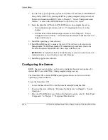
Page 42: ...iant Essentials Foundation Pack that ships with the server IMPORTANT To benefit from the Pre Failure Warranty on processors hard drives and memory modules you must install and use Insight Manager 11 Install any application software Configuring the Server RBSU the server setup utility can be used to configure the server and options To initiate RBSU press the F9 key when prompted during start up The...

Page 43: ... 322383 001 Last Saved On 2 11 03 1 22 PM 4 With the labeled side up insert the SmartStart CD into the CD ROM drive When the activity LED on the CD ROM illuminates green the SmartStart sequence begins For more information refer to the SmartStart CD Registering the Server Register the server by completing the forms included with the server or refer to the HP website register hp com ...

Page 44: ...llation procedure Improper grounding can cause electrostatic discharge Preparation Procedures To install internal hardware options you must do the following 1 Power down the server Refer to Powering Down the Server in Chapter 2 Server Operations 2 Remove the front bezel Refer to Removing the Front Bezel in Chapter 2 Server Operations 3 Remove the access panel Refer to Removing the Access Panel in ...

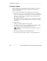
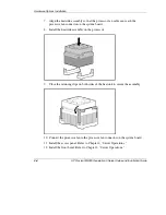
Page 45: ... to a higher speed no switch changes are needed on the system board The system ROM automatically sets the processor frequency during POST To install a processor 1 Complete the Preparation Procedures in this chapter 2 Be sure that the server has the most current ROM version To update the ROM visit the HP website www compaq com support files server us CAUTION Failure to flash the ROM before installi...

Page 46: ...ever The guide posts and directional key marks on the socket must be aligned with the corresponding slots and marks on the processor HP ProLiant ML330 Generation 3 Server Setup and Installation Guide 4 3 HP CONFIDENTIAL Writer Rob Weaver File Name e ch4 Hardware Options Installation doc Codename Flashback Part Number 322383 001 Last Saved On 2 11 03 1 24 PM ...

Page 47: ...to secure the assembly 10 Connect the processor fan to the processor fan connector on the system board 11 Install the access panel Refer to Chapter 2 Server Operations 12 Install the front bezel Refer to Chapter 2 Server Operations 4 4 HP ProLiant ML330 Generation 3 Server Setup and Installation Guide HP CONFIDENTIAL Writer Rob Weaver File Name e ch4 Hardware Options Installation doc Codename Flas...

Page 48: ...d support CAS Latency 2 5 CL 2 5 Do not mix ECC and non ECC SDRAM DIMMs If different types of DIMMs are mixed the server will not properly function The server supports 128 MB 256 MB 512 MB and 1 GB DIMMs Install DIMMs one at a time sequentially in DIMM slots 1 through 4 To install a DIMM 1 Complete the Preparation Procedures in this chapter HP ProLiant ML330 Generation 3 Server Setup and Installat...

Page 49: ...ly seated b Insert the DIMM into the slot c Close the DIMM slot latches NOTE The latches may close automatically when the DIMM is properly inserted 3 Install the access panel Refer to Chapter 2 Server Operations 4 Install the front bezel Refer to Chapter 2 Server Operations 4 6 HP ProLiant ML330 Generation 3 Server Setup and Installation Guide HP CONFIDENTIAL Writer Rob Weaver File Name e ch4 Hard...

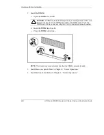
Page 50: ...ecognize these changes If the system configuration is incorrect the server does not work properly and you may receive error messages on the screen Removing Bezel Blanks When installing a device other than a hard drive into a removable media bay you must remove the corresponding bezel blank from the front bezel To remove a bezel blank 1 Power down the server Refer to Powering Down the Server in Cha...

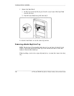
Page 51: ... in the removable media bays can be used to mount internal 3 5 inch devices The rails mounted inside the drive trays can be removed and used to mount other devices in the removable media bays When installing a device into a removable media bay you must first remove the drive tray 4 8 HP ProLiant ML330 Generation 3 Server Setup and Installation Guide HP CONFIDENTIAL Writer Rob Weaver File Name e ch...

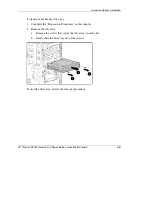
Page 52: ...t secure the drive tray on each side b Gently slide the drive tray out of the chassis To install a drive tray reverse the removal procedure HP ProLiant ML330 Generation 3 Server Setup and Installation Guide 4 9 HP CONFIDENTIAL Writer Rob Weaver File Name e ch4 Hardware Options Installation doc Codename Flashback Part Number 322383 001 Last Saved On 2 11 03 1 24 PM ...

Page 53: ...ce For SCSI devices set the SCSI ID on the drive You must manually set the SCSI ID on each device to a unique value in the range of 0 to 6 for each SCSI bus Refer to the documentation provided with the device for instructions on how to set the SCSI ID For ATA devices be sure that the jumper on the drive is set to Cable Select CS so that the drive device ID is determined by the cable For more infor...

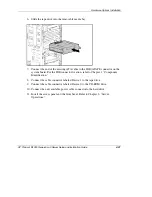
Page 54: ... terminated NOTE Using a non LVD single ended SCSI device affects the SCSI bus performance of the server Any SCSI devices that are Wide Ultra or older are single ended 6 Locate the hard drive screws on the front of the chassis HP ProLiant ML330 Generation 3 Server Setup and Installation Guide 4 11 HP CONFIDENTIAL Writer Rob Weaver File Name e ch4 Hardware Options Installation doc Codename Flashbac...

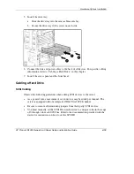
Page 55: ...ed in step 3 9 Connect the data and power cables to the back of all devices For specific cabling information refer to Cabling a Hard Drive in this chapter 10 Install the access panel and the front bezel Refer to Chapter 2 Server Operations 4 12 HP ProLiant ML330 Generation 3 Server Setup and Installation Guide HP CONFIDENTIAL Writer Rob Weaver File Name e ch4 Hardware Options Installation doc Code...

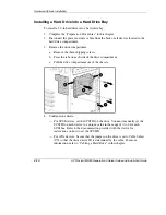
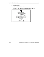
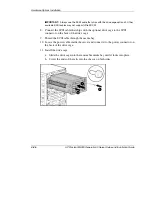
Page 56: ...ntation provided with the device for instructions on how to set the SCSI ID For IDE ATAPI or ATA devices be sure that the jumper on the drive is set to Cable Select CS so that the drive device ID is determined by the cable For more information refer to Cabling a Hard Drive in this chapter 3 Locate the hard drive screws on the front of the chassis HP ProLiant ML330 Generation 3 Server Setup and Ins...

Page 57: ... Secure the drive with four screws on the bottom of the drive tray 4 14 HP ProLiant ML330 Generation 3 Server Setup and Installation Guide HP CONFIDENTIAL Writer Rob Weaver File Name e ch4 Hardware Options Installation doc Codename Flashback Part Number 322383 001 Last Saved On 2 11 03 1 24 PM ...

Page 58: ...ver As a general rule a maximum of seven devices may be added per channel The server is equipped with one integrated Wide Ultra3 SCSI channel Be sure to remove all terminating jumpers from third party SCSI devices You must manually set the SCSI ID on each device to a unique value in the range of 0 through 6 for each SCSI bus Refer to the documentation provided with the device for instructions on h...

Page 59: ...ecommends connecting any non LVD single ended tape drives or SCSI devices to a separate SCSI cable to avoid a decrease in Ultra2 or Ultra 3 SCSI device performance A separate SCSI expansion board should be installed to accommodate single ended drives drives which are not Ultra2 Ultra 3 or greater NOTE The SCSI controller only operates in expansion slot 1 4 16 HP ProLiant ML330 Generation 3 Server ...

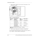
Page 60: ...es should be set to Cable Select CS enabling primary and secondary devices to be determined by the cable Connect ATA hard drives only to the Integrated ATA 100 RAID controller channels Do not connect other peripherals to the Integrated ATA 100 RAID controller channels To cable an ATA hard drive 1 Complete the hardware installation procedure 2 Connect the end of the ATA cable to the system board HP...

Page 61: ...er Device 1 Hard drive bay 3 4 ATA 100 RAID secondary controller Device 1 Media bay 4 Note For drive bay locations refer to Chapter 1 Component Identification 4 Connect the next available power cable connector to the hard drive For more information about connecting ATA cables refer to Drive Connection Tips in Chapter 6 RAID Configuration and Management 4 18 HP ProLiant ML330 Generation 3 Server Se...

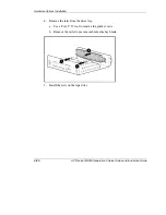
Page 62: ...I ID For IDE ATAPI or ATA devices be sure that the jumper on the drive is set to Cable Select CS so that the drive device ID is determined by the cable For more information refer to Cabling a Hard Drive in this chapter NOTE When installing an ATAPI tape drive refer to Cabling an ATAPI Tape Drive in Chapter 5 Server Cabling 3 Remove the drive tray Refer to Removing a Media Bay Drive Tray in this se...

Page 63: ...s b Remove the rails from a removable media bay blank 5 Install the rails on the tape drive 4 20 HP ProLiant ML330 Generation 3 Server Setup and Installation Guide HP CONFIDENTIAL Writer Rob Weaver File Name e ch4 Hardware Options Installation doc Codename Flashback Part Number 322383 001 Last Saved On 2 11 03 1 24 PM ...

Page 64: ...beled Device 1 to the tape drive 9 Connect the cable connector labeled Device 0 to the CD ROM drive 10 Connect the next available power cable connector to the hard drive 11 Install the access panel and the front bezel Refer to Chapter 2 Server Operations HP ProLiant ML330 Generation 3 Server Setup and Installation Guide 4 21 HP CONFIDENTIAL Writer Rob Weaver File Name e ch4 Hardware Options Instal...

Page 65: ... two screws b Remove the screws from the bezel c Remove the bezel from the drive cage IMPORTANT Be sure that the unit identification numbers 0 and 1 appear on the right side of the drive cage front panel For identification purposes the number 2 appears on the back of the bezel shipped with the option kit 3 Reverse the actions in step 1 to install the smaller bezel from the option kit on the drive ...

Page 66: ...nks from media bays 2 and 3 a Remove the screws from the blanks b Remove the blanks from the bays HP ProLiant ML330 Generation 3 Server Setup and Installation Guide 4 23 HP CONFIDENTIAL Writer Rob Weaver File Name e ch4 Hardware Options Installation doc Codename Flashback Part Number 322383 001 Last Saved On 2 11 03 1 24 PM ...

Page 67: ...stall the CD ROM drive in media bay 3 CAUTION Use care when sliding the CD ROM drive into the bay Excess force can damage the system board 4 24 HP ProLiant ML330 Generation 3 Server Setup and Installation Guide HP CONFIDENTIAL Writer Rob Weaver File Name e ch4 Hardware Options Installation doc Codename Flashback Part Number 322383 001 Last Saved On 2 11 03 1 24 PM ...

Page 68: ...cage and the left hand rail on the right side of the drive cage 7 Install the rails a Position the rails and two guide screws in the lower mounting holes on each side of the drive cage b Tighten the screws HP ProLiant ML330 Generation 3 Server Setup and Installation Guide 4 25 HP CONFIDENTIAL Writer Rob Weaver File Name e ch4 Hardware Options Installation doc Codename Flashback Part Number 322383 ...

Page 69: ...e media bay 10 Locate the power cable inside the server and connect it to the power connector on the back of the drive cage 11 Install the drive cage a Slide the drive cage into the removable media bay until it locks into place b Screw the ends of the rails into the chassis on both sides 4 26 HP ProLiant ML330 Generation 3 Server Setup and Installation Guide HP CONFIDENTIAL Writer Rob Weaver File ...

Page 70: ...ete the Preparation Procedures in this chapter 2 From inside the chassis push the expansion slot cover through the rear of the chassis 3 Depending on the length of the expansion card do one of the following If the card is full length go to step 4 If the card is half length go to step 5 HP ProLiant ML330 Generation 3 Server Setup and Installation Guide 4 27 HP CONFIDENTIAL Writer Rob Weaver File Na...

Page 71: ...w b Turn the retainer back towards the front of the chassis 4 28 HP ProLiant ML330 Generation 3 Server Setup and Installation Guide HP CONFIDENTIAL Writer Rob Weaver File Name e ch4 Hardware Options Installation doc Codename Flashback Part Number 322383 001 Last Saved On 2 11 03 1 24 PM ...

Page 72: ...1 Last Saved On 2 11 03 1 24 PM 5 Install the expansion board a Insert the expansion board into the slot b Secure the board with a screw 6 Connect any cables to the expansion board 7 For a full length expansion board install the expansion board retainer Reverse the actions in step 4 8 Install the access panel and front bezel Refer to Chapter 2 Server Operations To remove an expansion board reverse...

Page 73: ... on RBSU not found in this guide refer to the HP ROM Based Setup Utility User Guide found in the ProLiant Essentials Foundation Pack Navigating RBSU To make selections within RBSU use the following keys Access RBSU by pressing the F9 key when prompted during startup Use the arrow keys navigate through the menu system Make selections by pressing the Enter key HP ProLiant ML330 Generation 3 Server S...

Page 74: ...ies of menu selections designed to configure specific areas of the server The primary menus are as follows System Options PCI Devices Standard Boot Order IPL Boot Controller Order Date and Time Automatic Server Recovery ASR Server Passwords Server Asset Text Advanced Options BIOS Serial Console Utility Language 5 2 HP ProLiant ML330 Generation 3 Server Setup and Installation Guide HP CONFIDENTIAL ...

Page 75: ...e drive When disabled Diskette Write Control Diskette Boot Control and IPL Boot Order are irrelevant Embedded NIC Port 1 PXE Support enables the Pre boot Execution Environment PXE support for NIC Port 1 The Embedded NIC Port PXE Support option allows the server to boot to the network and attach to a PXE server with boot images When enabled the NIC port is displayed in the Initial Program Loader IP...

Page 76: ... is used to set the server date and time Automatic Server Recovery The Automatic Server Recovery menu configures the Automatic Server Recovery ASR features and may include the following options ASR Status enables or disables ASR When set to Disabled no ASR features function ASR Timeout sets a timeout limit for resetting a server that is not responding When the server has not responded in the selec...

Page 77: ...ons occur The local keyboard does not function unless the power on password is entered When a diskette is not in the diskette drive the power on password is bypassed allowing the server to start When a diskette is in the diskette drive the server does not start unless the power on password is entered locally NOTE Network Server Mode cannot be enabled until a power on password has been established ...

Page 78: ...lowing selections are available on this menu MPS Table Mode is automatically set based on the operating system selected and is used for interrupt routing By default this setting is Auto Set Table POST Speed Up quickens POST by disabling the extended power up memory test By default this setting is Enabled POST F1 Prompt configures the server so that when an error is encountered during the power up ...

Page 79: ...processors that can execute multiple tasks simultaneously using shared hardware resources of a single processor By default this setting is Enabled BIOS Serial Console Menu The BIOS Serial Console option allows you to configure the serial port to view POST error messages and run RBSU remotely through a serial connection to the server COM port The server that you are remotely configuring does not re...

Page 80: ...re the array settings To change any ORCA default settings and override the auto configuration process press the F8 key when prompted By default the auto configuration process configures the system for a Microsoft Windows 2000 operating system and the English language To change any default settings in the auto configuration process such as the settings for language operating system and primary boot...

Page 81: ...two separate 1 MB ROMs In the standard implementation one side of the ROM contains the current ROM program version while the other side of the ROM contains the backup version Safety and Security Benefits When you flash the system ROM ROMPaq writes over the backup ROM and saves the current ROM as a backup enabling you to switch easily to the existing ROM version if the new ROM becomes corrupted for...

Page 82: ...on of the system configuration switch refer to Chapter 1 Component Identification 5 Power up the server Refer to Chapter 2 Server Operations The ROM will beep and halt when the ROM images have been swapped 6 Power down the server and reset all system configuration switch positions to the default Off position 7 Power up the server If both the current and previous versions of the ROM are corrupted r...

Page 83: ...iciently upgrade system or controller ROM images across a wide range of servers and array controllers This tool has the following features Works offline and online Supports Microsoft Windows NT Windows 2000 Windows Server 2003 Novell Netware and Linux operating systems IMPORTANT This utility supports operating systems that may not be supported by the server For operating systems supported by the s...

Page 84: ...P provides legacy USB functionality at POST RBSU Diagnostics DOS Environments which do not support USB natively For more information on ProLiant USB support refer to the HP website www compaq com products servers platforms usb support html SmartStart Software The SmartStart CD is used to load the server software thereby achieving a well integrated server and ensuring maximum dependability and supp...

Page 85: ...drive with the labeled side up Handle the CD by its edges not by the flat surfaces of the disc 5 When the busy indicator turns green the SmartStart sequence begins Refer to the SmartStart documentation included with the server to install the operating system create updated driver diskettes and run upgrade utilities For more information about SmartStart software refer to the HP website www hp com s...

Page 86: ...stics LX32 Utility refer to the SmartStart CD or refer to the HP website www hp com servers manage For more information refer to the Management CD in the ProLiant Essentials Foundation Pack Drivers The server includes new hardware that may not have driver support on all operating system installation media If you are installing a SmartStart supported operating system use the SmartStart software and...

Page 87: ...s Management agents monitor key subsystems that are instrumental in making health configuration and performance data available to the agent software The agents act upon that data by initiating alarms in the event of faults The agents also provide updated management information such as network interface or subsystem performance statistics to the management systems For additional information refer t...

Page 88: ...n At the same time the Insight Manager 7 console notifies you by sending a message to a designated pager number that ASR 2 has restarted the system You can disable ASR 2 from the Insight Manager 7 console or through RBSU Survey Utility Survey Utility gathers critical hardware and software information on servers running Microsoft Windows NT Novell NetWare SCO OpenServer or SCO UnixWare operating sy...

Page 89: ...ts in the IML in several ways including the following From within Insight Manager 7 From within Survey Utility From within operating system specific IML viewers For NetWare IML Viewer For Windows Event Viewer or IML Viewer For Linux IML Viewer Application From within Enterprise Diagnostics LX32 Utility For more information refer to the Servers Troubleshooting Guide on the Documentation CD or the M...

Page 90: ... data from the remaining data drives RAID Terminology IMPORTANT Only RAID levels 0 1 and 1 0 are supported by the Integrated ATA RAID Configuration Utility RAID 0 Stripe RAID 0 is a RAID level that involves breaking up data into smaller blocks and then writing a block to each drive in the array striping RAID 0 does not provide any data redundancy but does offer the best performance of any RAID lev...

Page 91: ...ipes data and parity information across drives and requires a minimum of three hard drives Spare The spare option in the utility assigns an extra unused drive as a spare to be used in case of a drive failure The spare drive will not be used during normal system operation and provides no additional storage capacity A pre configured spare hard drive is brought into service only in the case of a RAID...

Page 92: ...DMA modes 0 2 and Ultra DMA modes 0 5 0 5 for ATA 100 Support for RAID levels 0 1 and 1 0 Multiple drive rebuilding Special handling of spare drive and rebuilding Using the Configuration Utility After all hard drives have been installed and connected press the F8 key during startup to run the Integrated ATA RAID Configuration Utility and view the setup screen IMPORTANT If you do not run the config...

Page 93: ...y configuration is selected Refer to Help Information for more information about arrays Physical Drive Information The Physical Drive Information window displays all the physical drives connected to the ATA 100 controller channels and their properties Press the up arrow and down arrow keys to navigate this window This window is not editable Help Information IMPORTANT When running the Configuration...

Page 94: ...ID mode including RAID 0 RAID 1 RAID 1 0 and Spare The default for the Array Type option is RAID 0 Drive s selects the drives for the array This option refers to the drive number listed in the Physical Drives Information box not the number of drives in the array Use the arrow keys and then press the spacebar to select or deselect the drive or drives Press the Enter key when done There is no defaul...

Page 95: ...ing write cache may cause data loss or corruption during an unexpected loss of power DMA ON enables or disables DMA direct memory access transfers in which data is transferred directly from the memory to the hard drive without microprocessor intervention Pressing the F7 key allows you to enable or disable these options Press the F7 key move the cursor to the desired box and then press the spacebar...

Page 96: ...Management Utility Once installed and running no user intervention is required for the use of the Integrated ATA RAID Management Utility The utility runs automatically at boot time If you must shut down the utility for any reason such as updating to a newer version follow OS specific instructions in this section Microsoft Operating Systems Right click on the Spy tray icon a small round character w...

Page 97: ...RAID Configuration Utility lists it as being in a Rebuilding state If this inconsistency occurs the array must be rebuilt If you add drives to a configuration the Integrated ATA RAID Management Utility tray icon which is seen only under Microsoft operating systems may indicate yellow or red depending on the array condition The color change indicates one of the following situations Errors are prese...

Page 98: ...ith similar capability in terms of speed and capacity Do not use dissimilar drives on the same channel Always use 80 conductor Ultra ATA cables Be sure that proper jumper settings are used For more information refer to Chapter 1 Component Identification Do not connect any ATAPI devices such as CD ZIP or LS120 to the ATA controller Configuration and Setup Tips To change the array configuration back...

Page 99: ...On 2 11 03 1 28 PM To respond to an unexpected message such as Drives Missing or Configuration Mismatch power down the server and check all connections ATA cables and power cables To respond to a Configuration Mismatch message after adding new drives press the F8 key to go to the setup and create the array configuration as needed The message displays because the new drives had been used before and...

Page 100: ...lished Radio Frequency RF emission limits to provide an interference free radio frequency spectrum Many electronic devices including computers generate RF energy incidental to their intended function and are therefore covered by these rules These rules place computers and related peripheral devices into two classes A and B depending upon their intended installation Class A devices are those that m...

Page 101: ...at personal expense Class B Equipment This equipment has been tested and found to comply with the limits for a Class B digital device pursuant to Part 15 of the FCC Rules These limits are designed to provide reasonable protection against harmful interference in a residential installation This equipment generates uses and can radiate radio frequency energy and if not installed and used in accordanc...

Page 102: ...C declaration contact Hewlett Packard Company P O Box 692000 Mail Stop 510101 Houston Texas 77269 2000 or call 281 514 3333 To identify this product refer to the part series or model number found on the product Modifications The FCC requires the user to be notified that any changes or modifications made to this device that are not expressly approved by Hewlett Packard Company may void the user s a...

Page 103: ...h the EMC Directive 89 336 EEC and the Low Voltage Directive 73 23 EEC issued by the Commission of the European Community and if this product has telecommunication functionality the R TTE Directive 1999 5 EC Compliance with these directives implies conformity to the following European Norms in parentheses are the equivalent international standards and regulations EN 55022 CISPR 22 Electromagnetic ...

Page 104: ...ice BSMI Notice HP ProLiant ML330 Generation 3 Server Setup and Installation Guide A 5 HP CONFIDENTIAL Writer Rob Weaver File Name h appa Regulatory Compliance Notices doc Codename Flashback Part Number 322383 001 Last Saved On 2 11 03 1 30 PM ...

Page 105: ... make adjustments or perform procedures to the laser device other than those specified herein Allow only authorized service technicians to repair the laser device Compliance with CDRH Regulations The Center for Devices and Radiological Health CDRH of the U S Food and Drug Administration implemented regulations for laser products on August 2 1976 These regulations apply to laser products manufactur...

Page 106: ...e product Laser Information Laser Type Semiconductor GaAIAs Wave Length 780 nm 35 nm Divergence Angle 53 5 degrees 0 5 degrees Output Power Less than 0 2 mW or 10 869 W m 2 sr 1 Polarization Circular 0 25 Numerical Aperture 0 45 inches 0 04 inches HP ProLiant ML330 Generation 3 Server Setup and Installation Guide A 7 HP CONFIDENTIAL Writer Rob Weaver File Name h appa Regulatory Compliance Notices ...

Page 107: ... than 60 C 140 F Do not disassemble crush puncture short external contacts or dispose of in fire or water Replace only with the spare parts designated for this product Batteries battery packs and accumulators should not be disposed of together with the general household waste To forward them to recycling or proper disposal please use public collection system or return them to HP or to authorized r...

Page 108: ... the wire must be a minimum of 1 00 mm or 18AWG and the length of the cord must be between 1 8 m 6 feet and 3 6 m 12 feet If you have questions about the type of power cord to use contact your authorized service provider IMPORTANT Route power cords so that they will not be walked on or pinched by items placed upon or against them Pay particular attention to the plug electrical outlet and the point...

Page 109: ...d hand contact by transporting and storing products in static safe containers Keep electrostatic sensitive parts in their containers until they arrive at static free workstations Place parts on a grounded surface before removing them from their containers Avoid touching pins leads or circuitry Always be sure you are properly grounded when touching a static sensitive component or assembly HP ProLia...

Page 110: ...puter chassis Wrist straps are flexible straps with a minimum of 1 megohm 10 percent resistance in the ground cords To provide proper ground wear the strap snug against the skin Use heel straps toe straps or boot straps at standing workstations Wear the straps on both feet when standing on conductive floors or dissipating floor mats Use conductive field service tools Use a portable field service k...

Page 111: ...he Servers Troubleshooting Guide on the Documentation CD HP ProLiant ML330 Generation 3 Server Setup and Installation Guide C 1 HP CONFIDENTIAL Writer Rob Weaver File Name j appc Server Error Messages doc Codename Flashback Part Number 322383 001 Last Saved On 2 11 03 1 34 PM ...

Page 112: ...e the server boots it must complete POST before it can load the operating system and start running software applications If the server completes POST and attempts to load the operating system refer to Problems After Initial Power Up in this appendix WARNING A risk of personal injury exists from hazardous energy levels The installation of options and the routine maintenance and service of this prod...

Page 113: ...ers Troubleshooting Guide NOTE If the server is rebooting repeatedly be sure that the server is not restarting due to an Automatic Server Recovery 2 ASR 2 power up caused by another problem Check Insight Manager 7 for notification of this event Refer to the Servers Troubleshooting Guide for more information 4 Restart the server 5 Check for the following normal power up sequence to be sure that the...

Page 114: ...ette drive SCSI devices if applicable ATA devices if applicable Option ROM d The operating system loads to complete the boot process If the problem persists continue with the section Diagnostic Steps in this appendix HP ProLiant ML330 Generation 3 Server Setup and Installation Guide D 3 HP CONFIDENTIAL Writer Rob Weaver File Name k appd Server Specific Troubleshooting doc Codename Flashback Part N...

Page 115: ...tion Question 1 Is the system power LED amber If yes press the Power On Standby button and then continue to question 2 If no refer to Table D 2 Question 2 Is the system power LED green If yes continue to question 3 If no refer to Table D 3 Question 3 Is the internal health LED green If yes continue to question 4 If no refer to Table D 4 Question 4 Is the monitor displaying information If yes use t...

Page 116: ...e power supply is undamaged and is fully seated Be sure that the power supply cables are connected to the system board Be sure that the power button LED cable is connected to the system board and power button LED assembly Be sure that all pins on connectors and components are straight Refer to the Servers Troubleshooting Guide for further options regarding power and general hardware problems Conta...

Page 117: ... button LED assembly may need to be replaced Firmly press the Power On Standby button Be sure that the power supply is undamaged and is fully seated Be sure that all pins on connectors and components are straight Contact the authorized service provider for assistance Yes If the system power LED is green refer to Table D 4 D 6 HP ProLiant ML330 Generation 3 Server Setup and Installation Guide HP CO...

Page 118: ...smatched speed and or type A DIMM has experienced a multibit error No valid memory is in the system The SCSI cabling or terminator configuration is incorrect on the SCSI controller An overtemperature condition has occurred Use amber failure LEDs to identify Missing components Degraded components Failed components Improperly installed components Contact the authorized service provider for replaceme...

Page 119: ...nections Refer to the Servers Troubleshooting Guide for information on video problems Be sure that the switch settings on the system board are correctly set Clear NVRAM in RBSU Are there any audible indicators such as a series of beeps A series of beeps is the audible signal indicating the presence of a POST error message Refer to the Servers Troubleshooting Guide for a complete description of eac...

Page 120: ...structions on how to upgrade the operating system and its drivers Information on available recovery options and advice on minimizing downtime Use the tables in this section to troubleshoot server installation problems that occur after the initial startup Table D 6 System Cannot Load SmartStart Possible Cause Possible Solution A SmartStart requirement is not met The wrong version of SmartStart is b...

Page 121: ... RBSU 2 Set defaults and exit the utility 3 Rerun RBSU to check the system configuration For complete instructions on the use of RBSU refer to Chapter 5 Server Configuration and Utilities or refer to the HP ROM Based Setup Utility User Guide The diskette in the diskette drive is preventing the system from loading Remove the diskette Existing software is causing conflict 1 Clear the NVRAM and boot ...

Page 122: ...nu in RBSU and then select Erase NVRAM Boot Space Disk Table D 8 Server Cannot Load the Operating System Possible Cause Possible Solution Required operating system step was missed Follow these steps 1 Note at which phase the operating system failed 2 Remove any loaded operating system 3 Refer to the operating system documentation 4 Install the operating system again Installation problem occurred R...

Page 123: ...use of RBSU refer to Chapter 5 Server Configuration and Utilities or refer to the HP ROM Based Setup Utility User Guide System Configuration Reset It may be necessary at some time to clear and reset system configuration settings When the system configuration switch position 6 is set to the On position the server is prepared to erase all system configuration settings from both CMOS and NVRAM CAUTIO...

Page 124: ...Autorun Menu on the SmartStart CD 2 Power down the server Refer to Chapter 2 Server Operations 3 Insert the ROMPaq diskette 4 Power up the server Refer to Chapter 2 Server Operations a The server generates one long beep and two short beeps to indicate that you are in disaster recovery mode If the diskette is not in place the system continues to beep until a valid ROMPaq diskette is inserted b The ...

Page 125: ... Flashback Part Number 322383 001 Last Saved On 2 11 03 1 35 PM Other Information Resources For additional troubleshooting information refer to the HP ProLiant ML330 Generation 3 Server Maintenance and Service Guide and the Servers Troubleshooting Guide on the Documentation CD For information on warranties and service and support upgrades Carepack services refer to the HP website www hp com suppor...

Page 126: ...100 VAC to 199 VAC U S 200 VAC to 240 VAC International Rated input frequency 50 Hz to 60 Hz Rated input current 6 A 100 VAC to 199 VAC 3 A 200 VAC to 240 VAC Input power 462 W Output specifications Rated steady state power 300 W Maximum peak power 400 W HP ProLiant ML330 Generation 3 Server Setup and Installation Guide E 1 HP CONFIDENTIAL Writer Rob Weaver File Name l appe Server Specifications d...

Page 127: ... 36 PM Environmental Specifications Table E 2 Environmental Specifications Specification Value Temperature range Operating 50 F to 95 F 10 C to 35 C Shipping 40 F to 158 F 40 C to 70 C Maximum wet bulb temperature 82 4 F 28 C Relative humidity noncondensing Operating 10 to 90 Non operating 5 to 95 All temperature ratings shown are for sea level There is an altitude derating of 1 C per 300 m to 3 0...

Page 128: ...charge the battery Do not expose the battery to temperatures higher than 60 C 140 F Do not disassemble puncture crush short external contacts or dispose of in fire or water Replace only with the spare designated for this product To remove the component 1 Power down the server Refer to Powering Down the Server in Chapter 2 Server Operations 2 Remove the front bezel Refer to Removing the Front Bezel...

Page 129: ...ccess to the battery Refer to Chapter 4 Hardware Options Installation 5 Remove the battery a Press outward on the latch at the top of the battery holder to release the battery b Lift the battery away from the holder To replace the component reverse the removal procedure IMPORTANT Replacing the system board battery resets the system ROM to its default configuration After replacing the battery recon...

Page 130: ...ay dimensions 1 5 ATA 100 RAID connectors 1 8 bay locating 1 5 authorized reseller xiii eject button 1 2 auto configuration process 5 8 installing 4 24 Autorun Menu 5 13 LED 1 3 removing 4 24 Class 1 laser product A 6 B Class A regulations A 4 battery Class B regulations A 4 disposal A 8 clearance requirements location 1 8 rack server 3 2 recycling or disposal A 8 tower server 3 2 removing F 1 COM...

Page 131: ...shooting features 1 1 diagnostic tools 5 13 Federal Communications Commission FCC diagnostics utility 5 14 dimensions server E 1 compliance notice Class A A 2 DIMM failure LEDs 1 12 compliance notice Class B A 2 DIMM slots location 1 8 declaration of conformity A 3 DIMMs installing 4 5 notice A 1 disk mirroring 6 2 requirements A 3 disk striping 6 1 rules A 2 A 3 diskette boot control 5 3 firmware...

Page 132: ...IML Integrated Management Log 5 17 Initial Program Loader See IPL L Insight Manager 7 5 15 laser devices A 6 installation LEDs services 3 1 front panel 1 3 SmartStart 5 13 rear panel 1 7 installing server system board 1 11 factory installed operating system 3 8 LPT port settings 5 3 operating system purchased separately 3 9 M overview 3 7 rack server 3 6 Management Agents 5 15 Integrated ATA RAID ...

Page 133: ...RCA Option ROM Configuration for Arrays power up sequence POST D 2 preparation procedures for option installation 4 1 auto configuration process 5 8 overview 5 15 problems diagnosing See troubleshooting overtemperature LEDs 1 12 processor failure LEDs 1 11 processor fan connectors 1 8 P processor power connector LEDs 1 11 processor sockets location 1 8 parallel connector 1 6 processor installing 4...

Page 134: ...nternal two bay hot plug Server Passwords menu 5 5 cabling 4 26 System Options menu 5 3 installing 4 22 rear panel components 1 6 SCSI ID setting 1 10 rear panel LEDs 1 7 security recharge warning A 8 diskette write control 5 3 recycling battery A 8 network server mode 5 5 redundant ROM passwords 5 5 accessing 5 9 5 10 QuickLock 5 5 benefits 5 9 serial connector 1 6 defined 5 9 series number A 1 r...

Page 135: ...17 LEDs 1 11 RBSU 5 1 system configuration switch redundant ROM support 5 9 location 1 8 ROMPaq 5 11 settings 1 9 SmartStart 5 12 system configuration resetting D 12 system fan connector 1 8 V system ID switch 1 10 system power LED 1 3 vanadium pentoxide battery warning A 8 ventilation See also fan T rack server requirements 3 3 tower server requirements 3 2 tape drive installing 4 19 video connec...

Reviews: