background image

7.

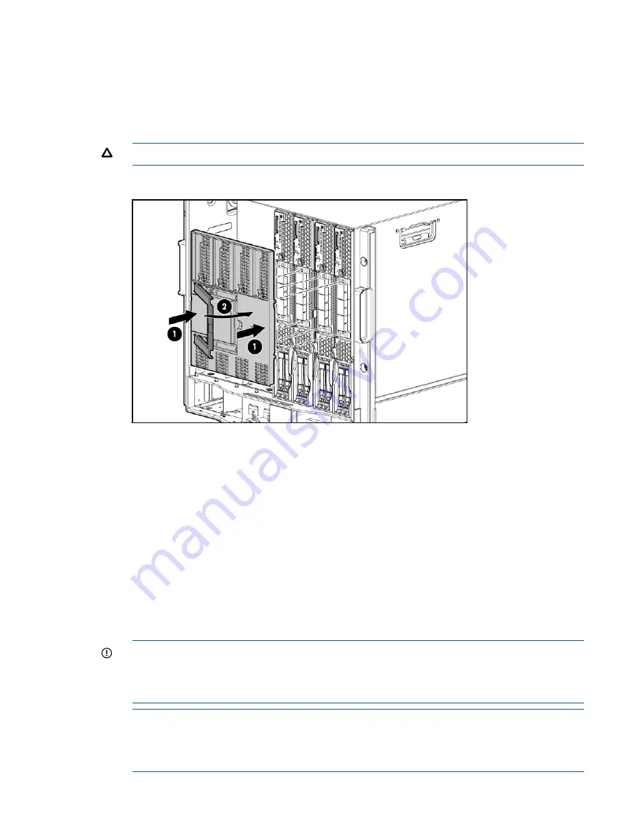
Push in the blue release latch on the handle to release the handle.

8.

Pull the handle all the way out

9.

Align the guide pins on the back of the Blade Link to the holes on the front of the server blades.
As you insert the pins into the holes, ensure the face on the Blade Link is evenly aligned parallel
to the face of the server blades.

10. Press firmly on the left and right sides of the Blade Link face until the handle naturally starts to

close.

CAUTION:

If not properly aligned, you can damage the Blade Link

11. Close the handle when it has engaged.

12. Log into iLO 3 on the Monarch blade. For more information, see the HP Integrity iLO3

Operations Guide.

13. In iLO 3, go to the Command Menu and execute

xd -r

to reboot all of the iLO 3s in the

conjoined set.

14. Run the conjoin checks

Integrity BL870c i4 and BL890c i4 systems go through a process called “conjoining” when
the Blade Link is attached. The system cannot boot until that process is completed properly.
a.

Execute the following CM commands in the iLO 3 TUI to show data from all blades. This
information can be used to determine if the blades are successfully conjoined:
i.

DF

— Lists the FRUs on all of the blades (2 or 4).

ii.

SR

— Shows a table of each blades firmware revisions.

iii.

Blade

— Shows information about the OA and the bays used.

b.

Check to see if the OA shows a properly conjoined system from its GUI.

IMPORTANT:

The secondary UUID and other system variables are stored on the Monarch

blade. If you do not put the Monarch blade in the leftmost slot, your system variables will not
match. If you ever change your iLO 3 configuration (such as adding users) that data is also
stored on the Monarch blade.

NOTE:

Auxiliary blades are not slot dependent after being installed and configured, however

when the conjoined systems ship, they come with A, B, C, D stickers located under the Blade
Links. While auxiliary blades are not slot dependent after being installed and configured, HP
recommends using the shipped order to ensure proper auxiliary blade function.

Installing the Blade Link for BL860c i4, BL870c i4 or BL890c i4 configurations

15

Summary of Contents for Integrity BL860c i4

Page 1: ...860c i4 BL870c i4 BL890c i4 Server Blade Installation Guide Abstract This document contains specific information that is intended for users of this HP product HP Part Number AM377 9003B Published August 2013 Edition 2 ...

Page 2: ...ogo are trademarks or registered trademarks of Intel Corporation or its subsidiaries in the United States and other countries UNIX is a registered trademark of The Open Group Microsoft and Windows are U S registered trademarks of Microsoft Corporation Warranty To get a copy of the warranty for this product see the warranty information website http bizsupport2 austin hp com bc docs support SupportM...

Page 3: ...ssing UEFI or the OS from iLO 3 MP 16 UEFI Front Page 17 Saving UEFI configuration settings 19 Booting and installing the operating system 19 Operating system is loaded onto the server blade 19 Operating system is not loaded onto the server blade 19 OS login prompt 19 Installing the latest firmware using HP Smart Update Manager 20 2 Support and other resources 21 Contacting HP 21 Before you contac...

Page 4: ...6 Access UEFI from iLO 3 MP 7 Download latest firmware and update using HP Smart Update Manager 8 Install and boot the OS 9 NOTE For more information regarding HP Integrity Server Blade upgrades see the HP Integrity BL860c i4 BL870c i4 BL890c i4 Server Blade User Service Guide for more information Installing and powering on the server blade Preparing the enclosure HP BladeSystem enclosures ship wi...

Page 5: ... divider 1 Slide the device bay shelf locking tab to the left to open it 2 Push the device bay shelf back until it stops lift the right side slightly to disengage the two tabs from the divider wall and then rotate the right edge downward clockwise Installing and powering on the server blade 5 ...

Page 6: ...3 Lift the left side of the device bay shelf to disengage the three tabs from the divider wall and then remove it from the enclosure 6 Installing the server blade into the enclosure ...

Page 7: ...Removing a c3000 device bay mini divider or device bay divider 1 Slide the locking tab down Installing and powering on the server blade 7 ...

Page 8: ...er toward the back of the enclosure until it stops b Slide the divider to the left to disengage the tabs from the wall c Rotate the divider clockwise d Remove the divider from the enclosure Installing interconnect modules For specific steps to install interconnect modules see the documentation that ships with the interconnect module 8 Installing the server blade into the enclosure ...

Page 9: ...pecific signals install an interconnect module in the bay corresponding to the embedded NIC or mezzanine signals Interconnect bay labels c3000 interconnect bay c7000 interconnect bay Server blade signal 1 1 NIC 1 Embedded 1 2 NIC 2 Embedded 1 1 NIC 3 Embedded 1 2 NIC 4 Embedded 2 3 and 4 Mezzanine 1 Installing and powering on the server blade 9 ...

Page 10: ...he server blade into the enclosure NOTE When installing additional blades into an enclosure additional power supplies might also be needed to meet power requirements For more information see the HP BladeSystem enclosure setup and installation guide for your product on the HP website http www hp com go bladesystem documentation NOTE Before installing and initializing the server blade install any se...

Page 11: ...nclosure to achieve the standby power state Server blades are set to power on to standby power when installed in a server blade enclosure Verify the power state by viewing the LEDs on the front panel and using Table 1 Table 1 Power States DC Power Applied Standby Power Applied Front Panel Power Button Activated Server Blade Installed in Enclosure Power States No Yes No Yes Standby power Yes Yes Ye...

Page 12: ...wer off blades in a conjoined configuration only power off the Monarch blade Use a virtual power button selection through the iLO 3 GUI Power Management Power Reset or the iLO 3 TUI commands This method initiates a controlled remote shutdown of applications and the OS before the server blade enter standby mode Press and release the Monarch power button This method initiates a controlled shutdown o...

Page 13: ...e blades NOTE If you will be upgrading an initial installation see the user service guide for more information on server blade upgrades Blade Link bay location rules Partner blade half height bay number Server blade full height bay number Partner blade support Blade location rules Supported enclosures Number of conjoined blades Class Bottom half height adjacent bay paired Yes No specific bay locat...

Page 14: ... HP BladeSystem c3000 Enclosure Setup and Installation Guide CAUTION Using the incorrect Blade Link can cause damage to the Blade Link and to the connectors on both the Blade Link and the server blades IMPORTANT Failure to follow bay location rules can prevent server blade power on NOTE The manufacturing part numbers for the Blade Link is located on a sticker on the PCA For more information see th...

Page 15: ...completed properly a Execute the following CM commands in the iLO 3 TUI to show data from all blades This information can be used to determine if the blades are successfully conjoined i DF Lists the FRUs on all of the blades 2 or 4 ii SR Shows a table of each blades firmware revisions iii Blade Shows information about the OA and the bays used b Check to see if the OA shows a properly conjoined sys...

Page 16: ...erver blade OS and the server blade firmware UEFI provides a standard environment for booting an OS and running preboot applications Use this procedure to access UEFI or the OS from the iLO 3 MP Your security parameters were set regarding remote access 1 Retrieve the factory iLO 3 password from the iLO 3 Network pull tag located on the right side of the Monarch blade 2 From the MP Main Menu enter ...

Page 17: ... has a factory installed OS you can interrupt the boot process to configure your specific UEFI parameters If you are at the UEFI shell prompt go to UEFI Front Page page 17 If you are at the OS login prompt go to OS login prompt page 19 UEFI Front Page If you are at the UEFI shell prompt enter exit to get to the UEFI Front Page To view boot options or launch a specific boot option press B or b to l...

Page 18: ...anager This is an advanced feature and should only be performed when directed To perform maintenance on the system such as adding deleting or reordering boot options press M or m to launch the Boot Maintenance Manager 18 Installing the server blade into the enclosure ...

Page 19: ...s loaded onto the server blade If the OS is loaded on your server blade normally UEFI will automatically boot to the OS If the UEFI Front Page is loaded press ENTER to start auto boot or B or b to select a specific boot option for your OS Use your standard OS logon procedures or see your OS documentation to log on to your OS Operating system is not loaded onto the server blade There are two option...

Page 20: ...duces any downtime required for the update process HP Smart Update Manager does not require an agent for remote installations Key features of HP Smart Update Manager are GUI and CLI command line interface Dependency checking which ensures appropriate installation order and dependency checking between components Intelligent deployment deploys only required updates Support for updating firmware on n...

Page 21: ...s see the Contact HP United States webpage http welcome hp com country us en contact_us html To contact HP by phone Call 1 800 HP INVENT 1 800 474 6836 This service is available 24 hours a day 7 days a week For continuous quality improvement calls may be recorded or monitored If you have purchased a Care Pack service upgrade call 1 800 633 3600 For more information about Care Packs refer to the HP...

Page 22: ...d with HP Systems Insight Manager A dedicated server is recommended to host both HP Systems Insight Manager and HP Insight Remote Support Advanced Details for both versions are available at http www hp com go insightremotesupport To download the software go to Software Depot http www software hp com Select Insight Remote Support from the menu on the right New and changed information in this editio...

Page 23: ...l result in data loss data corruption or damage to hardware or software IMPORTANT This alert provides essential information to explain a concept or to complete a task NOTE A note contains additional information to emphasize or supplement important points of the main text Typographic conventions 23 ...

Page 24: ...er replaceable unit CSR Control status registers D DDNS Dynamic domain name system DHCP Dynamic host configuration protocol DLL Dynamic link library DMA Direct memory access DMDC Data multiplexer demultiplexer controller DNS Domain name system E EFI Extensible Firmware Interface See also UEFI EMS Event management service ESD Electrostatic discharge F FC Fibre Channel FPL Forward progress log FRU F...

Page 25: ...ircuit assembly PCI Peripheral component interface PCI X Peripheral component interconnect extended PCIe Peripheral component interconnect express POL Point of load POSSE Pre OS system startup environment POST Power On Self Test Q QPI Intel QuickPath Interconnect S SAL System abstraction layer SAS Serial attached SCSI SATA Serial ATA SBA System bus adapter SEL System event log SFM System fault man...

Page 26: ... Extensible Firmware Interface replaces EFI UID Unit identification UPS Uninterruptible power supply USB Universal serial bus V VCM Virtual Connect Manager vMedia Virtual media VRM Voltage regulator module W WBEM Web Based enterprise management 26 Standard terms abbreviations and acronyms ...

Page 27: ...бладнання відповідає вимогам Технічного регламенту щодо обмеження використання деяких небезпечних речовин в електричному та електронному обладнанні затвердженого постановою Кабінету Міністрів України від 3 грудня 2008 1057 Warranty information HP ProLiant and X86 Servers and Options http www hp com support ProLiantServers Warranties HP Enterprise Servers http www hp com support EnterpriseServers W...

Page 28: ...ing off server blade 12 powering on default automatically 1 1 12 server blade 1 1 12 R regulatory information 27 Turkey RoHS material content declaration 27 Ukraine RoHS material content declaration 27 S server blade 12 enclosure interconnect mapping 9 powering on 1 1 12 T Turkey RoHS material content declaration 27 U UEFI accessing from iLO 3 MP 16 Front Page 17 saving configuration settings 19 U...

Reviews: