


10.
Install the air baffle.
11.
Install the access panel.
12.
Return the server to an upright position.
13.
Close and lock the tower bezel.
14.
Connect the power cord to the power source and server.
15.
Power on the server.
The server exists standby mode and applies full power to the system. The system power LED changes from
amber to green.
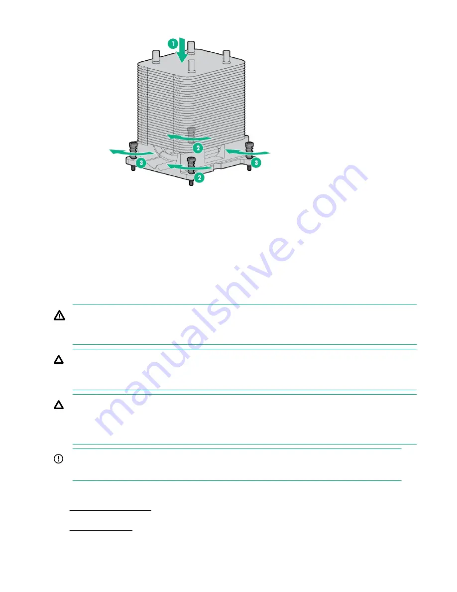
Replacing a processor
WARNING:
To reduce the risk of personal injury from hot surfaces, allow the drives and internal system components
to cool before touching them.
CAUTION:
To avoid damage to the processor and system board, only authorized personnel should attempt to
replace or install the processor in this server.
CAUTION:
To prevent damage to electrical components, take the appropriate anti-static precautions before
beginning any installation, removal or replacement procedure. Improper grounding can cause
electrostatic discharge.
IMPORTANT:
If installing a processor with a faster speed, update the system ROM before installing the processor.
Procedure
1.
2.
Disconnect the power cord from the power source and the server.
3.
.
52
Replacing a processor


