


3-24
Chapter 3
Gauging and Making Connections
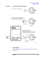
Gauging Techniques
To zero a gauge, review the instructions in
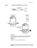
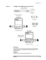
Connecting 7 mm Gauges
Fully extend the connector sleeve on one of the connectors and fully
retract the sleeve on the other. The extended sleeve creates a cylinder
into which the second connector fits.
If one of the connectors is fixed (as on a test port), fully extend that
connector sleeve (spin its knurled connector nut to make sure the
threads are fully extended). Fully retract the connector sleeve on the
other connector.
1. Remove the 7 mm collet from the center conductor with the collet
extractor tool.
2. Carefully align the connectors.
3. As you bring one connector up to the other, and as you make the
actual connection, be sure the connectors align perfectly.
4. Push the connectors straight together. Do not twist or screw them
together.
5. Engage the connector nut over the threads on the second connector.
Turn only the connector nut. Let the connector nut pull the two
connectors straight together.
NOTE
At this point, you want a connection in which the outer conductors
make gentle contact at all points on both mating surfaces. This requires
very light finger pressure.
6. Relieve any side pressure on the connection from long or heavy
devices or cables. This assures consistent torque while making the
final connection.
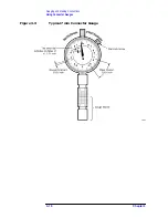
7. Hold the torque wrench with your thumb and index finger behind
the groove in the handle.
8. Tighten the connection until the handle begins to break at the
torque setting (see technique in
necessary to fully break the handle of the torque wrench to reach the
specified torque.
Reverse the order of the steps above to disconnect the device.
Type-N Gauge
See
“Connecting Type-N and 3.5 mm Gauges” on page 3-27
information.