background image


26 

Installing a switching fabric module 

Every 12910 AC switch has six switching fabric module slots numbered 10 through 15. For the proper 

operation of the switch, at least one switching fabric module must be installed in slot 10, slot 11, or slot 

12. 
The gray edged switching fabric module slots of a 12910 AC switch are located at the rear panel. The 

switching fabric modules are horizontally oriented. When installing a switching fabric module, make sure 

its PCB faces up. 
To install a switching fabric module: 

1.


Wear an ESD-preventive wrist strap, and make sure it makes good skin contact and is well 
grounded. For more information, see "

Attaching an ESD-preventive wrist strap

." 

2.


Remove the filler panel (if any) from the target slot. Keep the filler panel for future use. See 

Figure 

17

3.


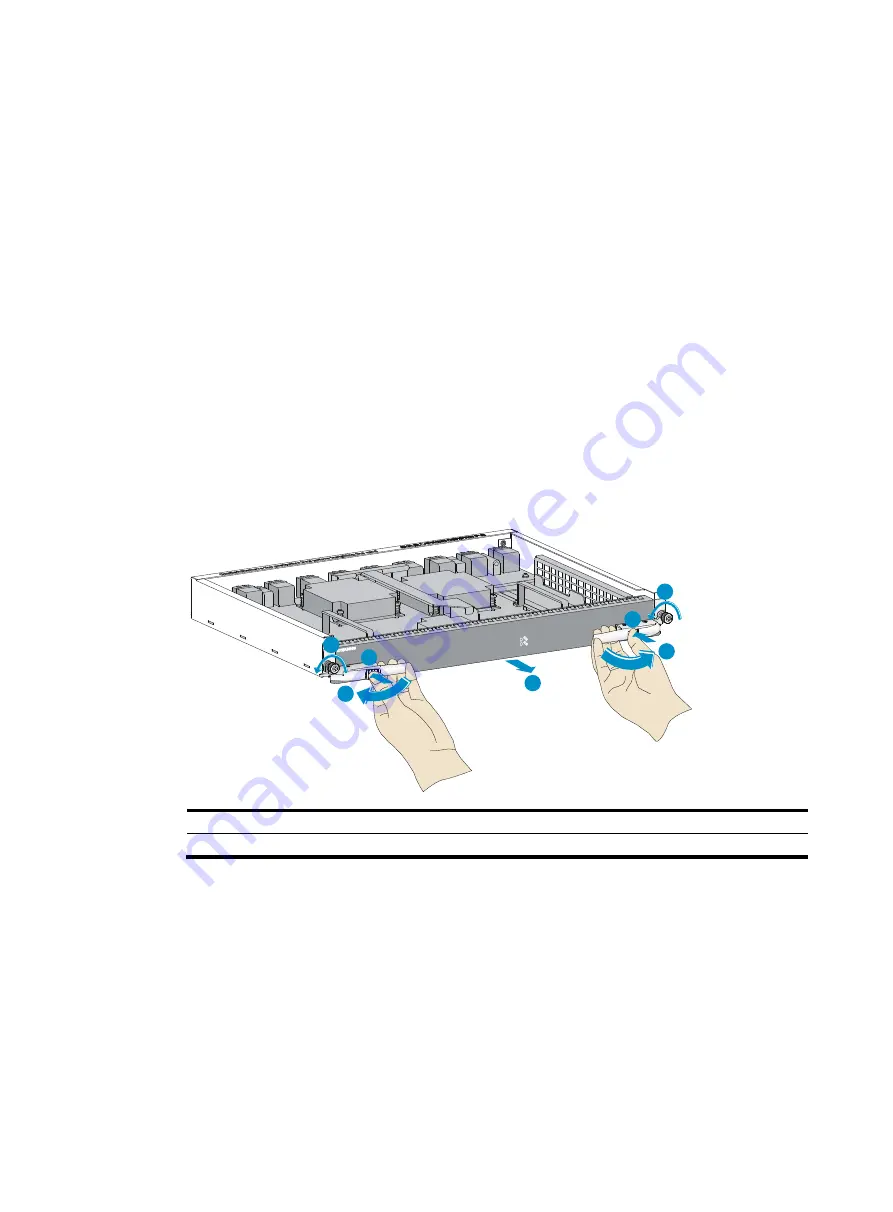
Loosen the captive screws on the protection box, hold the ejector levers on the switching fabric 
module, pressing the buttons on the levers, pull the ejector levers outward, and pull out the module 

from the protection box. See 

Figure 20

Keep the protection box for future use. 

Figure 20


Removing the protection box 


(1) Loosen the captive screws 

(2) Press down the buttons 

(3) Pull the ejector levers outward 

(4) Pull out the switching fabric module 


4.


Hold the switching fabric module by the front panel with one hand and support its bottom with the 

other. Slide the switching fabric module steadily into the target slot along the guide rails. 
Do not touch the components on the PCB. 

5.


As shown in callout 1 in 

Figure 21

, push the switching fabric module until the brakes on the ejector 

levers touch the slot edges tightly. 

6.


As shown in callout 2 in 

Figure 21

, press the ejector levers inward until the ejector levers touch the 

panel tightly and the switching fabric module seats into the backplane  

7.


As shown in callout 3 in 

Figure 21

, fasten the captive screws on the switching fabric module. 

1

1

2

2

3

3

4

Summary of Contents for FlexFabric 12900 series

Page 1: ...HP FlexFabric 12900 Switch Series Installation Guide Part number 5998 4376 Document version 5W100 20130815 ...

Page 2: ...MATERIAL INCLUDING BUT NOT LIMITED TO THE IMPLIED WARRANTIES OF MERCHANTABILITY AND FITNESS FOR A PARTICULAR PURPOSE Hewlett Packard shall not be liable for errors contained herein or for incidental or consequential damages in connection with the furnishing performance or use of this material The only warranties for HP products and services are set forth in the express warranty statements accompan...

Page 3: ...lling cage nuts 16 Mounting the switch to the rack 17 Grounding the switch 18 Grounding the switch with a grounding strip 18 Grounding the switch through the PE wire of an AC power supply 19 Installing FRUs 21 Attaching an ESD preventive wrist strap 21 Installing a card 22 Installing an MPU LPU 23 Installing a switching fabric module 26 Installing a power supply 27 Installing a power supply 28 Con...

Page 4: ...8 No terminal display 48 Garbled terminal display 49 Troubleshooting the switch during the operation 49 Power supply system failure 49 Fan failure 50 MPU failure 51 LPU and switching fabric module failure 51 Interface failure 52 Replacement procedures 53 Replacing a power supply 53 Replacing a card 55 Replacing an MPU or LPU 56 Replacing a switching fabric module 58 Replacing a fan tray 60 Removin...

Page 5: ...sted pair cable 87 Optical fiber 88 Optical fiber 88 Optical fiber cable 88 Patch cord 88 Pigtail cord 89 Fiber connector 89 Precautions 89 SFP cable 90 QSFP cable 90 QSFP to SFP cable 91 Appendix E Engineering labels 92 Labels for cables 92 Labels for network cables 92 Labels for power cables 92 Generic labels 93 Labels for devices 94 Filling in labels 94 Affixing labels 94 Affixing a label to a ...

Page 6: ...able 108 Removing the twisted pair and optical fiber 109 Repackaging the switch accessories 109 Repackaging the plastic panel 109 Repackaging the power supply 110 Repackaging the card 110 Repackaging the switch chassis 110 Removing the chassis from the rack 110 Removing the power cable bracket 111 Repackaging the switch chassis 112 Support and other resources 114 Contacting HP 114 Subscription ser...

Page 7: ...o not wear loose clothing jewelry for example necklace or any other things that could get caught in the chassis when you install and maintain the switch Electricity safety Clear the work area of possible electricity hazards such as ungrounded power extension cables missing safety grounds and wet floors Locate the emergency power off switch in the room before installation so you can quickly shut po...

Page 8: ...aser light emitted from the optical fiber may hurt your eyes The HP FlexFabric 12900 switches are Class 1 laser products Examining the installation site The HP FlexFabric 12900 switches must be used indoors To ensure the normal operation and long service life of your switch the installation site must meet the requirements in this section Weight support Make sure the floor can support the total wei...

Page 9: ...tal parts Lasting low relative humidity is likely to result in loose screws due to washer contraction and even electrostatic discharge ESD which causes the circuits to fail Table 2 Humidity requirements Humidity Range Operating humidity 10 to 95 noncondensing Storage humidity 5 to 95 noncondensing Cleanness Dust buildup on the chassis may result in electrostatic adsorption which causes poor contac...

Page 10: ...your switch against lightning shocks interferences and ESD is essential to the operating reliability of your switch Make sure the resistance between the chassis and the ground is less than 1 ohm For more information about grounding the switch see Installing the switch Power Perform the following tasks to meet the power requirements 1 Calculate the system power consumption The system power consumpt...

Page 11: ...that the airflow design of the chassis meets the airflow design of the installation site Figure 1 Airflow through the 12910 AC chassis 1 Power supply air intake vents 2 Power supply air exhaust vents 3 Chassis air intake vents 4 Chassis air exhaust vents Space For easy maintenance follow these guidelines The equipment room is at least 3 m 9 84 ft high Reserve at least 1 m 3 28 ft of clearance betw...

Page 12: ...u use a rack with a depth of 1 2 m 3 94 ft You must reserve at least 155 mm 6 10 in of clearance between the front rack post and the front door The depth of the switch is 1080 mm 42 52 in by calculating together the depth of chassis the cable management bracket and the power cable bracket For more information see Figure 2 ...

Page 13: ...7 Figure 2 Clearances required for a 12910 AC chassis ...

Page 14: ...the power cable bracket 5 Clearance between the chassis and the front door 6 Clearance between the chassis and the rear door 7 Minimum requirement to the rack depth 8 Cool air intake direction 9 Hot air exhaust direction 10 Front clearance required for replacing modules 11 Rear clearance required for replacing modules ...

Page 15: ... and enough clearance is reserved for cable routing The switch is ready for installation and has been carried to a place near the rack and convenient for moving Attaching installation accessory kits to the chassis Accessory kits Table 5 12910 AC accessory kits Accessory kit Description Mounting bracket Located at the two sides of the chassis to secure the chassis to the rack as shown in callout 1 ...

Page 16: ...lies and connect power cables first For installation of the plastic panels see Attaching the plastic panel Figure 3 12910 AC installation accessory kits 1 Mounting bracket 2 Cable management bracket 3 Plastic panel 4 Power supply slot Attaching the power cable bracket Every 12910 AC switch provides a power cable bracket at the lower part of the rear panel to secure the power cables To attach the p...

Page 17: ...holes 5 Fasten the screws Attaching the plastic panel Every 12910 AC switch provides a plastic panel at the lower part of the front panel to protect the air intake vents and power supply slots Before installing the plastic panel install power supplies and connect power cables first To install the plastic panel 1 Unpack the plastic panel and two clips As shown in Figure 5 use the screws supplied wi...

Page 18: ...locking tabs on the two sides of the plastic panel position the plastic panel with the positioning pins on the cover and attach it to the chassis Figure 6 Installing the plastic panel Attaching slide rails and cage nuts to the rack Installing slide rails If the rack has slide rails skip this section 1 2 3 ...

Page 19: ...et and the power cable bracket which are 830 mm 32 68 in 150 mm 5 91 in and 100 mm 3 94 in respectively To ensure stability of the rack install the slide rails to the lowest possible position when installing a single switch on the rack To install multiple switches on the rack mount the heaviest switch at the bottom of the rack Identify the rack position for the switch For the height and other spec...

Page 20: ...ard installation holes You can distinguish them by the space between each two holes The space between a standard installation hole and an auxiliary installation hole is wider than that between two adjacent standard installation holes Figure 8 Locating the rack position for installing slide rails 1 Middle of the narrower metal area between holes 3 Install six cage nuts in the square holes in each r...

Page 21: ...ly and adjust its length until the installation holes on the rear end of the slide rail touch the cage nuts on the rear rack post Then screw in screws and fasten Insert a screw in each mounting hole of the slide rail to ensure its weight bearing capacity 6 Repeat steps 4 and 5 to install the other slide rail Make sure the two slide rails are at the same height so that the switch can be placed on t...

Page 22: ... rack post according to the mounting holes on the mounting bracket Each mounting hole on the mounting bracket corresponds to one cage nut The mounting brackets have been installed to the chassis when a 12910 AC switch is shipped You can remove a mounting bracket to determine cage nut installation positions or use a tool a long ruler for example to locate installation positions of cage nuts accordi...

Page 23: ...ack CAUTION Do not hold the handle of an FRU for example the fan tray or the air vents of chassis Any attempt to carry the switch with these parts may cause equipment damage or even bodily injury After placing the switch on the slide rails do not leave go of your hands immediately because this may tip the switch damaging the switch or even causing bodily injury To mount the switch to the rack 1 Mo...

Page 24: ...ssis to the rack 1 Slide the chassis into the rack 2 Fasten the screws If the mounting holes in the mounting brackets cannot align with the cage nuts on the rack verify that the bottom edge of the slide rail aligns with the middle of the narrower metal area between holes and that the cage nuts are installed in the correct holes Grounding the switch CAUTION Before you use the switch connect the gro...

Page 25: ...the ring terminal of the grounding cable to the grounding post of the grounding strip and fasten the grounding cable to the grounding strip with the hex nut Figure 14 Connecting the grounding cable to a grounding strip 1 Grounding sign 2 Attach the grounding screws with dual hole terminals to the grounding holes 3 Grounding strip 4 Grounding post 5 Ring terminal 6 Hex nut Grounding the switch thro...

Page 26: ...PE wire of the AC power supply is well grounded at the power distribution room or AC power supply transformer side In addition make sure the PE connector on the switch is well connected to the PE wire of the AC power supply Figure 15 Grounding the switch through the PE wire of the AC power supply ...

Page 27: ...ive wrist strap and make sure it is well grounded when installing modules To use an ESD preventive wrist strap 1 Make sure the switch is well grounded For how to ground your switch see Installing the switch 2 Put on the wrist strap 3 Tighten the wrist strap to keep good skin contact Make sure the resistance reading between your body and the ground is between 1 and 10 megohms 4 As shown in Figure 1...

Page 28: ...All cards of the HP FlexFabric 12900 switch are hot swappable For compatibility between the HP FlexFabric 12900 switches and all cards see Appendix B FRUs and compatibility matrixes After all cards are installed start the switch to view the status LEDs on the MPU to examine the running status of the cards If a RUN LED is flashing the card in the slot is operating correctly For more information abo...

Page 29: ...n either empty MPU slot For an LPU install it in any empty LPU slot The pink edged MPU slots of a 12910 AC switch are located at the rear panel The MPUs are horizontally oriented When installing an MPU make sure its PCB faces up The purple edged LPU slots of a 12910 AC switch are located at the front panel They are vertically oriented When installing an LPU make sure its PCB faces left The install...

Page 30: ...ptive screws on the protection box of the LPU pull the ejector levers outward and pull out the LPU from the protection box See Figure 18 Figure 18 Removing the protection box 1 Loosen the captive screws 2 Pull the ejector levers outward 3 Pull out the LPU ...

Page 31: ...es on its ejector levers touch the slot edges tightly 6 As shown in callout 2 in Figure 19 press the ejector levers inward until the ejector levers touch the panel tightly and the LPU seats into the backplane 7 As shown in callout 3 in Figure 19 fasten the captive screws on the LPU Figure 19 Installing the LPU 1 Push the LPU into the slot until the brakes touch the slot edges tightly 2 Press the e...

Page 32: ...he ejector levers on the switching fabric module pressing the buttons on the levers pull the ejector levers outward and pull out the module from the protection box See Figure 20 Keep the protection box for future use Figure 20 Removing the protection box 1 Loosen the captive screws 2 Press down the buttons 3 Pull the ejector levers outward 4 Pull out the switching fabric module 4 Hold the switchin...

Page 33: ...ke sure the circuit breaker is off before installation When moving a power supply hold the two sides of the power supply with both hands to avoid damaging the power supply The HP FlexFabric 12900 switch uses N N dual line power supply or N 1 one line power supply power redundancy You can install appropriate number of power supplies according to the power supply mode and system consumption Strictly...

Page 34: ...ntact and is well grounded For more information see Attaching an ESD preventive wrist strap 2 Remove the protection cover if any from the chassis For more information see Replacement procedures 3 Unpack the power supply 4 As shown in callout 1 in Figure 23 install the power supply in a correct direction a Push the latch on the power supply outward and open the panel of the power supply b Select th...

Page 35: ...the power cable is switched off The power receptacles of a 12910 AC switch are located in the power distribution box area at the lower part of the rear panel They are numbered as PWR1 through PWR8 Make sure the numbers of the power receptacles are the same the slot numbers of the power supplies that have been installed To connect the power cable 1 Plug the power cable into the power receptacle of ...

Page 36: ...e lower part of the front panel For installing the protection cover see Installing the switch Figure 24 Securing the power cable Installing a transceiver module CAUTION Do not remove the dust cap from a transceiver module before connecting an optical fiber Remove the optical fiber if any from a transceiver module before installing it If no SFP SFP module or SFP cable is to be installed to the SFP ...

Page 37: ...til it has firm contact with the slot as shown in Figure 25 For a QSFP module that uses a plastic pull latch skip this step QSFP modules use either a metal or plastic pull latch They are installed in the same way except that you must pivot the clasp up for the module that uses a metal pull latch For an SFP module press the module down against the upward force of the bottom spring tab so you can pu...

Page 38: ... cables are hot swappable To connect an SFP QSFP or QSFP to SFP cable 1 Wear an ESD preventive wrist strap and make sure it makes good skin contact and is well grounded For more information see Attaching an ESD preventive wrist strap 2 Unpack the cable 3 Plug the cable connector into the port Make sure the cable connector is the right side up The bend radius of the cable must be at least eight tim...

Page 39: ...y high availability scalability and manageability For more information about IRF see HP FlexFabric 12900 Switch Series IRF Configuration Guide IRF fabric setup flowchart The setup flow is shown in Figure 26 For the actual procedure see HP FlexFabric 12900 Switch Series IRF Configuration Guide for the software release you are using Figure 26 IRF fabric setup flowchart To set up an IRF fabric ...

Page 40: ...abric 12900 Switch Series IRF Configuration Guide Planning IRF fabric setup This section describes issues that an IRF fabric setup plan must cover Planning IRF fabric size and the installation site Plan IRF fabric size and the installation site as follows 1 Use HP FlexFabric 12900 Switch Series IRF Configuration Guide as a reference to identify the number of member switches that your system softwa...

Page 41: ...neighboring IRF member switches you must connect the physical ports of IRF port 1 on one switch to the physical ports of IRF port 2 on the other switch A two member IRF fabric must use the daisy chain topology If the system software version you are using supports more than two IRF members you can create an IRF fabric that comprises more than two members in daisy chain topology or more reliably rin...

Page 42: ...verify the basic IRF settings For more information about configuring basic IRF settings see HP FlexFabric 12900 Switch Series IRF Configuration Guide Connecting the physical IRF ports Follow these guidelines when selecting transceiver modules and cables Use SFP transceiver modules and fibers for long haul connection or use SFP cables to connect SFP ports for short haul connection When connecting S...

Page 43: ...ement station See HP FlexFabric 12900 Switch Series Fundamentals Configuration Guide 4 Verify that you can manage all member switches as if they were one node 5 Display the running status of the IRF fabric by using the commands in Table 7 Table 7 Displaying and maintaining IRF configuration and running status Task Command Display information about the IRF fabric display irf Display topology inform...

Page 44: ...ports equals the number of MPUs in the IRF fabric An HP FlexFabric 12900 switch supports up to 16 concurrent VTY users Accessing the switch for the first time The first time you access the switch you must use a console cable to connect a console terminal for example a PC to the console port on the switch Setting up the configuration environment IMPORTANT Identify the mark on the console port and m...

Page 45: ...indows 7 Windows Vista or any other operating system prepare third party terminal control software and follow the software user guide or help to configure the terminal The following are the required terminal settings Bits per second 9600 Data bits 8 Parity None Stop bits 1 Flow control None Emulation VT100 To set terminal parameters for example on a Windows XP HyperTerminal 1 Select Start All Prog...

Page 46: ...e serial port to be used from the Connect using list and click OK Figure 30 Setting the serial port used by the HyperTerminal connection 4 Set Bits per second to 9600 Data bits to 8 Parity to None Stop bits to 1 and Flow control to None and click OK ...

Page 47: ...41 Figure 31 Setting the serial port parameters 5 Select File Properties in the HyperTerminal window Figure 32 HyperTerminal window 6 On the Settings tab set the emulation to VT100 and click OK ...

Page 48: ...filler panels All the network cables fibers power cables and grounding cables have been correctly connected The input power voltage meets the requirement of the switch The console cable is correctly connected the terminal or PC used for configuration has started and the configuration parameters have been set To power on the switch turn on the power source of the switch The following is a sample ou...

Page 49: ...1 bin Done Loading file flash 12900 cmw710 boot a0040sp01 bin Done Image file flash 12900 cmw710 boot a0040sp01 bin is self decompressing Done System is starting Line aux0 is available Press ENTER to get started Press Enter at the prompt When the prompt Sysname appears you can configure the switch After powering on the switch verify the following items The cooling system is working and you can hea...

Page 50: ...nfigure secure and flat user management Environments that do not need granular privilege management Username and password Complex to configure secure and hierarchical user management Environments where multiple user roles cooperate to manage the switch For more information about login methods see HP FlexFabric 12900 Switch Series Fundamentals Configuration Guide Configuring the basic access functi...

Page 51: ...figure static routes Configure a static route with the destination IP address 172 16 1 0 and the next hop IP address 192 168 0 2 Sysname ip route static 172 16 1 0 255 255 255 0 192 168 0 2 Configure VLANs Create VLAN 10 and enter its view Sysname vlan 10 Sysname vlan10 Assign port Ten GigabitEthernet 1 0 1 to VLAN 10 Sysname vlan10 port ten gigabitethernet 1 0 1 Sysname vlan10 quit Configure MSTP...

Page 52: ...ork Before you connect the switch to the network verify that all its basic network settings are correct WARNING To avoid injury to your eyes do not stare at the optical ports and optical fiber connectors when connecting optical fibers You can install a transceiver module see Installing FRUs in a fiber port and use optical fibers to connect the port to the network For more information about optical...

Page 53: ...u do not need to differentiate between the transmitter TX and receiver RX ports For other types of transceiver modules the Tx port on one end must connect to the RX port on the other end Testing connectivity After you plug the switch into the network use the ping or tracert command to test the network connectivity For more information about these commands see HP FlexFabric 12900 Switch Series Comm...

Page 54: ...s The MPU provides the LEDs for the fans power supplies and cards You can locate the failures according to the LED status on the MPU For more information about the LED status on the MPU see Appendix C LEDs The MPU or LPU of the switch provides the port status LEDs with which you can detect port failures For more information about the LED status on the LPU see Appendix C LEDs If you cannot locate f...

Page 55: ... is on and the FAIL LED is off on the power supplies the input and output LEDs are steady green For more information see Appendix C LEDs To view the power supply LEDs you must remove the plastic panel from the chassis For more information see Replacement procedures You can install up to eight power supplies to the 12910 AC switch When all the power supplies are operating correctly the OK LED is on...

Page 56: ...nt panel Both the MPU and the fan tray provide the fan tray LEDs including an OK LED and a FAIL LED NOTE Two fan tray slots are available on a 12910 AC switch One fan tray can fully meet heat dissipation requirement of the switch If only one fan tray is available install it in slot FAN2 If the FAN LED is red or the OK LED is off and the FAIL LED is on the fan tray has failed To troubleshoot the fa...

Page 57: ...ts contact HP Support NOTE On each 12910 AC switch The LPU slot numbers are marked above the slots on the front panel of the chassis The MPU and switching fabric module slot numbers are marked at the right side of the slots on the rear panel of the chassis LPU and switching fabric module failure The 12910 AC switch provides an NPU LED indicating the switching fabric module status and an LPU LED in...

Page 58: ...witching fabric module failure 2 Examine the cable connection of the interface For how to correctly connect the cable to an Ethernet interface see Connecting your switch to the network 3 Verify that the cable is in good condition Use the cable to connect two interfaces of the same type that operate correctly If the LEDs of the two interfaces are on the cable is normal Otherwise the cable fails Use...

Page 59: ...a circuit breaker to the power line for each power supply Before replacing a power supply turn off its circuit breaker The power supply may be of high temperature Remove it with caution To install the removed power supply to the chassis again install it after the status LED on it is off Figure 36 Power supply removal flow Figure 37 Power supply installation flow To replace a power supply 1 Prepare...

Page 60: ...astic panel 5 Push the latch at the lower left of the power supply outward and open the power supply panel 6 Hold both sides of the power supply to pull the power supply out 7 Close the power supply panel and push the latch inward ...

Page 61: ...on procedures see Installing FRUs 10 Install the plastic panel For more information see Installing the switch Replacing a card WARNING When replacing a card while the switch is running be aware of electrical safety hazards The replacement procedures of the cards on the HP FlexFabric 12900 switches are similar Before you replace a card remove all its cables If no new card is to be installed install...

Page 62: ...tatic mat to place the removed LPU 2 Wear an ESD preventive wrist strap and make sure it makes good skin contact and is well grounded For more information see Installing FRUs 3 Use a Phillips screwdriver to loosen the captive screw on the LPU as shown in callout 1 on Figure 40 4 Move the ejector levers outward to separate the LPU from the backplane as shown in callout 2 on Figure 40 ...

Page 63: ...ejector levers outward 1 Loosen the captive screw 2 Pull the ejector levers outward 5 Use one hand to slowly move the LPU outward Supporting the bottom of the LPU with the other hand pull the LPU out of the slot along slide rails as shown in Figure 41 ...

Page 64: ... switching fabric module 1 Prepare an antistatic mat to place the removed switching fabric module 2 Wear an ESD preventive wrist strap and make sure it makes good skin contact and is well grounded For more information see Installing FRUs 3 Use a Phillips screwdriver to loosen the captive screws on the switching fabric module as shown in callout 1 on Figure 42 ...

Page 65: ...n Figure 42 Figure 42 Loosening screw and moving the eject levers outward 1 Loosen the captive screw 2 Press the buttons on the ejector levers 3 Move the ejector levers outwards 5 Slowly move the switching fabric module outward Holding both sides of the switching fabric module pull the switching fabric module out of the slot along the slide rails as shown in Figure 43 ...

Page 66: ...jury do not touch the rotating fans when you replace the fan tray To avoid device damage and bodily injury HP recommends that you have two persons replace a fan tray When the fan tray fails replace the fan tray to ensure normal operation of the switch If only one fan tray is available for the 12910 AC switch install it to slot FAN2 Removing a fan tray CAUTION To ensure normal ventilation install a...

Page 67: ...s 3 Loosen the captive screws on the fan tray and pull the fan tray part way out of the chassis as shown in Figure 44 Figure 44 Pulling out a fan tray 4 After the fans stop rotating holding both sides of the fan tray take out the fan tray from the chassis as shown in Figure 45 Figure 45 Taking out a fan tray 5 Put the removed fan tray on the antistatic mat ...

Page 68: ... the fan tray in a correct direction a Align the fan tray with upside on top with the fan tray slot b Holding both sides of the fan tray gently slide the fan tray along the guide rails into the slot as shown in Figure 46 Figure 46 Sliding a fan tray into the slot c Holding the handle of the fan tray completely push the fan tray into the slot and fasten the captive screws on the fan tray as shown i...

Page 69: ... it makes good skin contact and is well grounded For more information see Installing FRUs 2 Remove the optical fibers on the module 3 Pivot the clasp outward For a QSFP module that uses a plastic pull latch skip this step QSFP modules use either a metal or plastic pull latch 4 Grasp the clasp on the module and carefully pull the module out of the slot 5 Put the dust plug on the removed module and ...

Page 70: ...cable cannot be removed smoothly or even the module or slot could be damaged To replace an SFP QSFP QSFP to SFP cable 1 Wear an ESD preventive wrist strap and make sure it makes good skin contact and is well grounded For more information see Installing FRUs 2 Gently press the cable connector in and then pull the pull latch on the cable outward to pull out the cable connector 3 Install a new cable ...

Page 71: ...lexFabric 12900 Switch Series includes only one model HP FlexFabric 12910 Switch AC Chassis An HP FlexFabric 12900 switch chassis has an LPU section power supply section fan tray section switching fabric module section and MPU section Figure 48 Front and rear views of the 12910 AC ...

Page 72: ...tem consumption You can install a power supply in any empty power supply slot 4 Fan tray slots Located at the rear of the switch Installed with fan trays for heat dissipation Two fan trays are shipped with the chassis Two fan tray slots are available on a 12910 AC switch If only one fan tray is available install it in slot FAN2 5 Switching fabric module slots Both switching fabric modules and swit...

Page 73: ...ds and power supplies When the switch is installed with all accessories cards power supplies and transceiver modules its maximum weight is 200 kg 440 92 lb Make sure the slide rails can fully support this weight HP recommends that you order the HP X421 A Series Chassis Universal 4 Post Rack Mounting Kit JC665A which supports a weight up to 300 kg 661 38 lb Table 12 Card weights and dimensions Card...

Page 74: ...on of a card refers to the power consumed by the card when all the ports on the card are link up and send broadcasts Table 15 Card power consumption Model Minimum static power consumption Maximum dynamic power consumption LSX1SUP10A1 45 W 50 W LSX1TGS48EA1 310 W 435 W LSX1QGS16EA1 345 W 450 W LSX1FAB10B1 135 W 170 W Fan tray power consumption The switch uses fans with the automatic speed adjustmen...

Page 75: ... To calculate heat dissipation of the switch assume 90 power consumption is converted to heat and the efficiency of the power supply is 90 Heat dissipation hour of the switch is 0 9 total power consumption of the cards plus power consumption of the fan tray 0 9 3 4121 For the power consumption of the cards and fan trays of the HP FlexFabric 12900 switches see Module power consumption and system po...

Page 76: ... LSX1SUP10A1 specifications Item Description Interfaces One console port One 10 100 1000BASE T interface for management and upgrade One USB port Interface transmission rate Console port No greater than 1 15200 bps and defaults to 9600 bps 10 100 1000BASE T interface 10 100 1000 Mbps half full duplex Cables and max transmission distance Console port 15 m 49 21 ft over common asynchronous serial int...

Page 77: ...AC switch chassis Table 23 Switching fabric module ordering guide Chassis model Available switching fabric module model 12910 AC LSX1FAB10B1 Table 24 Switching fabric product code and model matrix Switching fabric model Product code HP Description LSX1FAB10B1 JG623A HP FlexFabric 12910 3 84Tbps Type B Fabric Module Power supplies The 12910 AC switch supports the HP 12500 2000W AC Power Supply JF42...

Page 78: ...er supply is automatically powered on Fan trays The HP FlexFabric 12900 switch comes with two fan trays installed Order the fan trays compatible with your switch if necessary Table 26 Fan tray specifications Chassis model Applicable fan tray Number of fans Fan diameter Maximum rotating speed Maximum air flow rate 12910 AC 12910 fan tray 5 200 mm 7 87 in 7700 RPM 1750 CFM 350 CFM per fan Table 27 F...

Page 79: ...isted in Table 30 QSFP modules listed in Table 31 QSFP cables listed in Table 32 QSFP to SFP cables listed in Table 33 Table 28 SFP module specifications Product code Description Central wavelength nm Fiber diameter μm Multimode fiber modal bandwidth MHz km Maximum transmission distance JD092B HP X130 10G SFP LC SR Transceiver 850 50 125 2000 300 m 984 25 ft 500 82 m 269 03 ft 400 66 m 216 54 ft 6...

Page 80: ... 1804 46 ft JD061A HP X125 1G SFP LC LH40 1310nm Transceiver 1310 9 125 N A 40 km 24 86 miles JD062A HP X120 1G SFP LC LH40 1550nm Transceiver 1550 9 125 N A 40 km 24 86 miles JD063B HP X125 1G SFP LC LH70 Transceiver 1550 9 125 N A 70 km 43 50 miles JD103A HP X120 1G SFP LC LH100 Transceiver 1550 9 125 N A 100 km 62 14 miles JD098B HP X120 1G SFP LC BX 10 U Transceiver TX 1310nm RX 1490nm 9 125 N...

Page 81: ...1610 Transceiver 1610 9 125 N A 70 km 43 50 miles IMPORTANT You must use the HP X120 1G SFP LC BX 10 U Transceiver JD098B and the HP X120 1G SFP LC BX 10 D Transceiver JD099B in pairs Table 31 QSFP module specifications Product code Description Connector Fiber specifications Multimode fiber modal bandwidth MHz km Maximum transmission distance JG325A HP X140 40G QSFP MPO SR4 Transceiver MPO MULTIMO...

Page 82: ...QSFP to 4x10G SFP 1m Direct Attach Copper Splitter Cable 1 m 3 28 ft Used for connecting a 40 Gbps QSFP port to four 10 Gbps SFP ports JG330A HP X240 40G QSFP to 4x10G SFP 3m Direct Attach Copper Splitter Cable 3 m 9 84 ft JG331A HP X240 40G QSFP to 4x10G SFP 5m Direct Attach Copper Splitter Cable 5 m 16 40 ft ...

Page 83: ...ent Ethernet port LEDs Fan LEDs Power supply status LED Card LEDs MPU active standby status LED LPU LEDs SFP port LED QSFP port LEDs Switching fabric module LEDs Fan tray status LEDs Power supply LEDs Chassis LEDs On a 12910 AC switch chassis LEDs are located at the upper part of the front panel which are PWR power supply LED FAN fan tray status LED MPU MPU LED NPU switching fabric module LED and ...

Page 84: ...Status Description PWR Green All installed power supplies are operating correctly Red At least one power supply is faulty Off The switch is not powered on Fan tray status LED Table 36 Fan tray LED description LED State Description FAN Green The installed fan trays are operating correctly Red A fan tray problem is present or no fan tray is in position Off The switch is not powered on ...

Page 85: ...dule LED description LED State Description NPU Green The installed switching fabric modules are operating correctly Red At least one switching fabric module is faulty or loading software Off The switch is not powered on or the switching fabric module has not started loading software LPU LED Table 39 LPU LED description LED State Description LPU Green The installed LPUs are operating correctly Red ...

Page 86: ... port is receiving or sending data On Off A link is present Off Off No link is present Fan LEDs The MPU provides two LEDs OK and FAIL to indicate the status of the fan tray Table 41 Fan LED description OK FAIL Description On Off All installed fan trays are operating correctly Off On A fan tray problem is present or no fan tray is in position Off Off The switch is not powered on Power supply status...

Page 87: ... version of the switch does not match that of the card Flashing 1 Hz Flashing 0 5 Hz The temperature of the card is higher than the alarm threshold Steady on Steady on The card is starting up or the card is faulty Off Off The card is not in position NOTE It is normal that the ALM LED for an LPU lights for a period of time at the initial phase of the system startup MPU active standby status LED The...

Page 88: ...ing fabric module has one RUN LED and one ALM LED to indicate its operating status Table 47 Switching fabric module LED description RUN LED ALM LED Description Flashing 1 Hz Off The switching fabric module is operating correctly Off Steady on The switching fabric module is faulty Flashing 1 Hz Steady on The switching fabric module is not operating correctly For example the temperature of the switc...

Page 89: ...4 Fault LED Table 49 Power supply LED description LED Status Description Power input LED green Steady on The power is being input correctly Off No power is being input Flashing The input power has exceeded the threshold Power output LED green Steady on The power is being output correctly Off No power is being output Flashing The power output is overloaded Over temperature alarm LED yellow Steady o...

Page 90: ...SFP cable QSFP port at one end and SFP port at the other end Connects QSFP port at one end and SFP port at the other end NOTE Use the Ethernet twisted pair cable to connect only the management Ethernet port of the 12910 AC switch Console cable A console cable is an 8 core shielded cable with a crimped RJ 45 connector at one end for connecting to the console port of the switch and a DB 9 female con...

Page 91: ...ased on performance Ethernet cables can be classified into category 3 category 4 category 5 category 5e category 6 and category 7 cable based on performance In LANs category 5 category 5e and category 6 are commonly used Table 51 Ethernet cable description Type Description Category 5 Transmits data at a maximum speed of 100 Mbps with a bandwidth of 100 MHz Category 5e Transmits data at a maximum s...

Page 92: ...in assignments Select an Ethernet twisted pair cable according to the RJ 45 Ethernet interface type on your device An RJ 45 Ethernet interface can be MDI for routers and PCs or MDIX for switches For the pinouts of RJ 45 Ethernet interfaces see Table 52 and Table 53 ...

Page 93: ... Bi directional data cable A 7 Reserved N A BIDC Bi directional data cable C 8 Reserved N A BIDC Bi directional data cable C To ensure normal communication the pins for sending data on one port should correspond to the pins for receiving data on the peer port When both of the ports on the two devices are MDI or MDIX a crossover Ethernet cable is needed A cross over cable connects devices of the sa...

Page 94: ...ler and has a lower modal dispersion It carries only a single ray of light It is mostly used for communication over longer distances Multi mode fiber It has a core size of 50 μm or 62 5 μm or higher and has a higher modal dispersion than single mode optical fiber It is mostly used for communication over shorter distances Table 54 Allowed maximum tensile force and crush load Period of force Tensile...

Page 95: ...which makes the optical system debugging and maintenance more convenient and the transit dispatching of the system more flexible Figure 56 MPO connector Figure 57 LC connector Precautions Make sure the fiber connector and fiber type match the transceiver module type The fiber ports on some cards have dust covers Remove the dust covers before using the fiber ports Fiber interfaces must be installed...

Page 96: ... or bending along the acute side of mechanical parts the fiber must wear jackets or cushions Insert and remove a plug with care Never exert a fierce force to the fiber or plug otherwise the plug may be damaged or the fiber may be broken Never pull press or extrude the fiber fiercely For the allowed maximum tensile load and crush load see Table 54 SFP cable You can use SFP cables to connect the SFP...

Page 97: ...to SFP cable A QSFP to SFP cable is a cable with one QSFP module at one end and four SFP modules at the other end Figure 60 QSFP to SFP cable 1 QSFP connector 2 QSFP pull latch 3 SFP connector 4 SFP pull latch ...

Page 98: ...r of the label to identify the peer end of the cable on which the label is affixed As shown in Figure 61 write a network cable label as follows Write the position of the cable in Area 1 Write the position of the cable on the peer end in Area 2 Area 3 is the part that is folded up inside the label when the label is affixed to the cable Figure 61 Label for network cables 1 Dividing line 2 Cut dotted...

Page 99: ...neric label is bar shaped with fixed dimensions It is applicable to all cables A mark TO is located at the upper left corner in the right area of the label to identify the peer end of the cable on which the label is affixed The meaning of the dividing lines is the same as labels for network cables ...

Page 100: ...on about using a label printer see the user guide of the printer To write labels use black markers A marker has two nibs Be sure to use the smaller nib to write labels Affixing labels After printing or writing a label remove the label from the bottom page and affix it to the network cable or the identification plate of the power cable Affixing a label to a network cable Typically a label is affixe...

Page 101: ...the recessed rectangular area on the identification plate You can stick the label to either side of the identification plate Be sure to affix the labels on the same side of the identification plates A cable tie is bundled 2 cm 0 79 in away from the connector You can affix the label to other positions as needed Figure 64 shows how to affix a label when a cable is laid horizontally TO B02 03 12 ...

Page 102: ...r on the right side of the cable in vertical cabling Make sure the label is facing out as shown in Figure 67 Figure 67 Affixed labels Affixing a generic label The requirements for affixing a generic label are the same as affixing a label on a network cable For more information see Affixing a label to a network cable For the example of affixed labels see Figure 65 TO B03 48V2 ...

Page 103: ...plate Bundle cable ties at the same positions of power cables with identification plates on the same side The positions of up down right or left are all based on the viewpoint of the engineering person who is working on the label Examples The label examples in this document are for reference only Engineering labels for twisted pair cables These labels are affixed to twisted pair cables that connec...

Page 104: ... the twisted pair cables are connecting For example On a label for the twisted pair cable that connects a switch and a server For the switch end Rack number chassis number and Ethernet port number on the switch For the server end Rack number and chassis number or the specific location of the server if the server is laid separately On a label for the twisted pair cable that connects the switch and ...

Page 105: ...d left right order with two digits for example 01 D Fiber port number Numbered in top down and left right order with two digits for example 05 R Optical receiving interface T Optical transmitting interface N A MN B C D R T MN Rack number The meanings are the same as above If the local device and the peer device are not in the same equipment room MN can be the name of the equipment room B Chassis n...

Page 106: ... 70 Example of a label on an optical fiber between two devices A01 01 05 05 R The local end of the optical fiber is connected to Optical Receiving Interface 05 on Slot 5 Chassis 01 in the rack on Row A Column 01 in the equipment room G01 01 01 01 T The peer end of the optical fiber is connected to Optical Transmitting Interface 01 on Slot 01 Chassis 01 in the rack on Row G Column 01 in the equipme...

Page 107: ...he same rule for the rack number Otherwise specify the detailed locations to avoid confusing with other sockets The label only carries location information about the peer equipment and the power socket while information of the local end is not necessary Make sure labels are affixed in the correct direction That is after the cable ties are bundled onto the cable the identification plates with the l...

Page 108: ...102 Figure 73 Example of a device label ...

Page 109: ...he network cables at the tie wrap tabs as shown in Figure 74 Bundle the power cables to the power cable bracket at the lower part of the rear panel and route the power cables depending on the equipment room conditions location of the power distribution cabinet lightning protection box and connector strip for example of the exchange office When you connect two cables together place the connector at...

Page 110: ...ure radius of a high speed cable for example SFP cable should be at least five times of the cable s outer diameter If the coaxial cable is frequently bent plugged and unplugged the curvature radius should be at least 10 times the cable s outer diameter Minimum curvature radius of fibers When the fiber is wrapped up around the cabling plate the diameter of the cabling plate should be at least 25 ti...

Page 111: ... signal cable bundle is at least 30 mm 1 18 in The cable management brackets and cable routing slots inside or outside the rack are smooth and have no sharp edges or tips When you route cables through sharp sheet metal penetration points or along sharp edges of mechanical parts use bushings or take any other action to protect the cables from being cut or abraded The sheet metal penetration points ...

Page 112: ...h slack in cables and make sure they are not stressed from any movement of the part Cables must be protected at points where they might rub or come in contact with sharp edges or heated areas Use high temperature cables near heat sources Securely fasten cables and take adequate measures to prevent loose connections Figure 79 Securely fastening cables 1 Flat washer 2 Spring washer 3 Nut Fasten heav...

Page 113: ... bundle diameter mm Space between bundles mm 10 80 to 150 10 to 30 150 to 200 30 200 to 300 Do not tie cables or bundles in a knot The metal parts of the crimped cold pressed terminal blocks such as air switch cannot protrude beyond the blocks ...

Page 114: ...cable tie that secures the power cable and then pull out the plug from the power distribution box Removing the console cable 1 Pull the RJ 45 connector of the console cable out from the console port of the switch 2 Pull the DB 9 connector of the console cable out from the serial port of the PC Removing the grounding cable 1 Loosen the two screws at the grounding holes located on the upper right of...

Page 115: ...h a dust cap to keep the connector clean Repackaging the switch accessories Repackaging the plastic panel Before you remove the power supply remove the plastic panel from the lower part of the front panel To repackage a plastic panel 1 Prepare the packing bag and box of the plastic panel Make sure the bag is clean dry and not damaged 2 Remove the plastic panel from the lower part of the front pane...

Page 116: ...rmation about how to remove a transceiver module see Replacement procedures 3 Remove all cards from the chassis slots If filler panels are shipped with the switch remove the chassis from the rack and install the filler panels to the corresponding empty slots For information about how to remove the chassis from the rack see Removing the chassis from the rack For information about how to remove a ca...

Page 117: ...chassis sides to completely remove the chassis from the rack 5 Put the chassis onto the wooden pallet base Figure 81 Removing the chassis from the rack 1 Loosen the captive screws that attach the mounting brackets to the rack 2 Slide the chassis outwards along the slide rails Removing the power cable bracket Before you repack the 12910 AC switch remove the power cable bracket The power cable brack...

Page 118: ...racket into the bag 4 Put the packed power cable bracket into the box Repackaging the switch chassis 1 Align the rear end of the chassis to the silkscreen frame on the wooden pallet base as shown in callout 1 of Figure 83 2 Attach the L type bracket with screws that are shipped with the switch to secure the chassis to the pallet base as shown in callout 2 of Figure 83 1 2 1 ...

Page 119: ...ase as shown in callout 3 of Figure 83 5 Cover the foam cushion to the chassis top and make sure the mounting brackets seat into the internal notches of the foam cushion 6 Erect one paper angle bead along each vertical edge of the chassis and use the carton to cover the chassis from top down with silkscreen side facing the front panel of the chassis 7 Put the box of packed accessories into the not...

Page 120: ...ing you will receive email notification of product enhancements new driver versions firmware updates and other product resources Related information Documents To find related documents browse to the Manuals page of the HP Business Support Center website http www hp com support manuals For related documentation navigate to the Networking section and select a networking category For a complete list ...

Page 121: ...eparated by vertical bars from which you select one choice multiple choices or none 1 n The argument or keyword and argument combination before the ampersand sign can be entered 1 to n times A line that starts with a pound sign is comments GUI conventions Convention Description Boldface Window names button names field names and menu items are in bold text For example the New User window appears cl...

Page 122: ... 2 features Represents an access controller a unified wired WLAN module or the switching engine on a unified wired WLAN switch Represents an access point Represents a security product such as a firewall a UTM or a load balancing or security card that is installed in a device Represents a security card such as a firewall card a load balancing card or a NetStream card Port numbering in examples The ...

Page 123: ...99 Engineering labels for twisted pair cables 97 ESD prevention 2 F Fan tray power consumption 68 Fan tray status LED 78 Fiber connector 89 G Garbled terminal display 49 General safety recommendations 1 Generic labels 93 Grounding 4 Grounding the switch through the PE wire of an AC power supply 19 Grounding the switch with a grounding strip 18 H Handling safety 1 Humidity 3 I Identifying physical ...

Page 124: ...ted pair and optical fiber 109 Repackaging the card 1 10 Repackaging the plastic panel 109 Repackaging the power supply 1 10 Repackaging the switch chassis 1 12 Replacing a switching fabric module 58 Replacing an MPU or LPU 56 Replacing an SFP QSFP QSFP to SFP cable 64 Replacing an SFP SFP QSFP module 63 RJ 45 connector 85 S Setting terminal parameters 39 Setting up the configuration environment 3...

Reviews: