


Fan sink
Fan sinks are available for models that use up to a 65 W processor and models that use a 95 W processor.
CAUTION:
The bond between the fan sink and the processor may be very tight.
If the computer will power on, before removing the fan sink, turn on the computer until it warms the fan sink.
Warming the fan sink lessens the bond between the heat sink and the processor, thereby making separating
them easier.
Make sure not to pull the processor out of the socket when you lift the fan sink, especially if you cannot warm
the fan sink prior to removal. Inadvertently removing the processor can damage the pins.
1.
Prepare the computer for disassembly (
Preparation for disassembly on page 17
).
2.
Remove the access panel (
3.
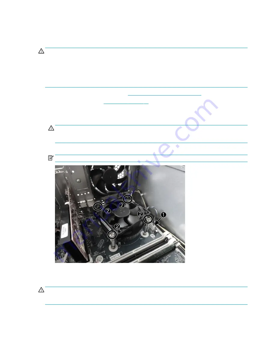
Disconnect the fan cable from the system board connector labeled CPUFAN (1).
4.
Loosen the four silver captive Torx T15 screws (2) that secure the fan sink to the system board.
CAUTION:
Remove fan sink retaining screws in diagonally opposite pairs (as in an X) to even the
downward forces on the processor. The pins on the socket are very fragile and any damage to them may
require replacing the system board.
5.
Lift the heat sink from atop the processor.
NOTE:
System board appearance may vary.
6.
Each time the heat sink is removed, thoroughly clean the thermal grease from the bottom of the heat
sink and apply fresh thermal grease to the top of the processor. Replacement thermal material is
included with the fan sink and system board spare part kits.
CAUTION:
Fan sink retaining screws should be tightened in diagonally opposite pairs (as in an X) to evenly
seat the fan sink on the processor. This is especially important as the pins on the socket are very fragile and
any damage to them may require replacing the system board.
Fan sink
55


