8Ć13
Troubleshooting
C3187Ć90000
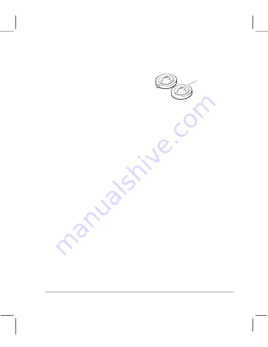
Misaligned Cartridge Caps
If a customer is complaining about shortened cartridge life or frequent cartridge failure, you
should check the cartridgeĆcap alignment (procedure below). This is especially true if the
problem is always happening to the same cartridge. A sure sign of a misaligned cap is excess
ink around the cap and inside the ink reservoir. You should clean the caps and reservoir
usingonly water. You should also clean the wiper.
Cartridge caps
Seating area
Function of the Cartridge Caps
The cartridge caps (also called serviceĆstation caps) are located in the service station.
Lookingclosely at a cartridge's printĆhead reveals two parallel rows of nozzles. The cap
should form a seal that surrounds the rows. If the caps are mispositioned, the seal may be
touchingone or more of the nozzles. The result is premature cartridge failure and a messy
service station.
What can Cause Cap Misalignment?
The most common cause is that the cap is not seated properly on the serviceĆstation sled.
Any of the serviceĆstation parts could cause misalignment if defective or installed incorrectly.
Checking CartridgeĆCap Alignment
The followingtools are recommended for this procedure:
D
Soft lintĆfree wipes
D
NonĆpermanent ink marker (dry erase type works best)
D
10X magnifier
D
Print cartridges
To check the alignment of the caps with respect to the printĆhead nozzles
,
Remove the window, center cover and left endcover.
.
Manually move the carriage out of the service station.
A
Load very clean cartridges into the carriage.
4
Apply ink to the seatingarea of the cartridge caps with the ink marker.
5
Manually move the carriage
slowly
into the service station, then out again.
6
Remove the cartridges and observe where the ink mark is positioned with respect to the
nozzles. A 10X magnifier is very useful for this step. If one is not available, you should
look at how centered the mark is within the gold pad area.
7
If the ink mark is touchingany nozzle, you need to check and reseat the cartridge caps
and repeat the test.
Summary of Contents for DesignJet 200
Page 1: ... ...
Page 3: ... ...
Page 14: ... ...
Page 15: ... ...
Page 19: ... ...
Page 22: ...2Ć4 Site Planning and Requirements C3187Ć90000 ...
Page 23: ... ...
Page 27: ... 4 1 2 3 4 5 6 mm 0 25 in 5 1 2 3 4 5 B A B A A B A B X X X ...
Page 31: ... ...
Page 33: ... ...
Page 65: ... ...
Page 139: ... ...
Page 149: ...8Ć0 8 Troubleshooting ...
Page 178: ...8Ć30 Removal and Replacement C3187Ć90000 ...
Page 179: ...9Ć0 9 Product History and Service Notes ...
Page 193: ...10Ć1 10 Parts and Diagrams ...
Page 197: ...10Ć5 Parts and Diagrams C3187Ć90000 Legs and Media Bin 1 2 3 3 4 5 6 7 1 3 4 3 3 3 3 3 8 8 ...
Page 199: ...10Ć7 Parts and Diagrams C3187Ć90000 Window Center and Bottom Covers To Carriage ...
Page 203: ...10Ć11 Parts and Diagrams C3187Ć90000 Left Endcover and Trim ...
Page 205: ...10Ć13 Parts and Diagrams C3187Ć90000 Right Endcover and Trim ...
Page 207: ...10Ć15 Parts and Diagrams C3187Ć90000 Carriage Axis Drive Left End ...
Page 209: ...10Ć17 Parts and Diagrams C3187Ć90000 Service Station 1 2 3 3 4 5 7 6 6 ...
Page 215: ...10Ć23 Parts and Diagrams C3187Ć90000 Media Drive Assemblies ...
Page 219: ...10Ć25 Parts and Diagrams C3187Ć90000 Bail and Overdrive Assemblies ...
Page 221: ...10Ć27 Parts and Diagrams C3187Ć90000 Pinch Arm Assembly ...
Page 227: ... ...
Page 231: ... ...
Page 244: ...IndexĆ04 C3087Ć90000 ...
Page 245: ... ...


