background image

When replacing the system board, be sure that the following components are removed from the
defective system board and installed on the replacement system board:

SIM (see 

SIM on page 42

)

WWAN module (see 

WWAN and GPS modules (select models only) on page 48

)

WLAN module (see 

WLAN module on page 50

)

Memory module (see 

Memory module on page 52

)

RTC battery (see 

RTC battery on page 53

)

Fan/heat sink assembly (see 

Fan/heat sink assembly on page 69

)

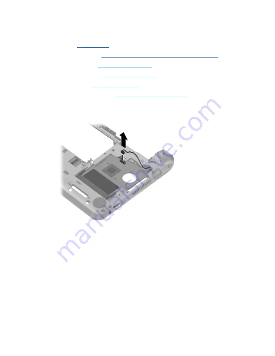
Remove the system board:

1.

Disconnect the power connector cable from the system board.

2.

Remove the 2 Phillips 2.0×4.0 screws 

(1)

 that secure the system board to the base enclosure.

3.

Lift the right side of the system board 

(2)

 until it rests at an angle.

Component replacement procedures

73

Summary of Contents for Compaq Mini 110

Page 1: ...HP Mini 110 Compaq Mini CQ10 Maintenance and Service Guide ...

Page 2: ...tion SD Logo is a trademark of its proprietor The information contained herein is subject to change without notice The only warranties for HP products and services are set forth in the express warranty statements accompanying such products and services Nothing herein should be construed as constituting an additional warranty HP shall not be liable for technical or editorial errors or omissions con...

Page 3: ...w another hard surface such as an adjoining optional printer or a soft surface such as pillows or rugs or clothing to block airflow Also do not allow the AC adapter to contact the skin or a soft surface such as pillows or rugs or clothing during operation The device and the AC adapter comply with the user accessible surface temperature limits defined by the International Standard for Safety of Inf...

Page 4: ...iv Safety warning notice ...

Page 5: ...2 Bottom components 13 Wireless antennas 14 Additional hardware components 15 3 Illustrated parts catalog 16 Service tag 16 Computer major components 17 Display components 23 Mass storage device 25 Miscellaneous parts 26 Sequential part number listing 27 4 Removal and replacement procedures 34 Preliminary replacement requirements 34 Tools required 34 Service considerations 34 Plastic parts 34 Cabl...

Page 6: ...lay assembly 61 Fan heat sink assembly 69 System board 71 Power connector cable 75 5 Setup Utility 77 Starting Setup Utility 77 Using Setup Utility 77 Changing the language of Setup Utility 77 Navigating and selecting in Setup Utility 78 Displaying system information 78 Restoring default settings in Setup Utility 78 Exiting Setup Utility 79 Setup Utility menus 79 Main menu 79 Security menu 79 Syst...

Page 7: ...discs 87 Backing up your information 87 Using Windows Backup and Restore 87 Using system restore points 89 When to create restore points 89 Create a system restore point 89 Restore to a previous date and time 89 8 Power cord set requirements 90 Requirements for all countries 90 Requirements for specific countries and regions 91 9 Recycling 92 Battery 92 Display 92 Index 98 vii ...

Page 8: ...viii ...

Page 9: ...l Graphics Media Accelerator 3150 Unified Memory Architecture UMA graphics subsystem Broadcom High Definition HD Enhanced Video Accelerator hardware decoder on board select models only and support for DVD playback from external drive or Flash streaming and playback of locally stored downloaded media files 128 MB buffer memory 64M 16 DDR3 1 piece 1 5V 800MHz DRAM Display The display assembly includ...

Page 10: ...35 cm 2 5 inch SATA hard drives 500 GB 7200 rpm 7 0 mm 320 GB 7200 and 5400 rpm 7 0 mm NOTE Supported only on computers with Windows 7 Starter with Notebook COA Emerging Markets Windows 7 Basic with Notebook COA for China Windows 7 Premium and Windows 7 Professional 250 GB 7200 and 5400 rpm 7 0 mm 160 GB 7200 and 5400 rpm 7 0 mm NOTE Supported on all operating systems Optical drive Supports extern...

Page 11: ...le select models only HP lc 2000 Mobile Broadband Module HP lc 2010 Mobile Broadband Module select models only 2 WWAN antennas built into display assembly select models only GPS by way of Broadcom GPS Mini Card select models only External media cards Digital Media Slot with push push technology supporting Memory Stick MS Memory Stick Pro MSP MultiMediaCard MMC Secure Digital SD Memory Card Secure ...

Page 12: ...AC adapter non Smart with localized cable plug support AC adapter connector on cable 1 0 m 3 3 ft power cord 3 cell Lithium ion Li ion battery 2 55 Ahr 28 Wh 6 cell Li ion high capacity battery 2 55 Ahr 55 Wh Security Kensington lock slot Operating system Windows 7 Starter Windows 7 Professional select countries Support for HP QuickWeb USB Key Recovery support for Service refurbish centers and rep...

Page 13: ...r identify the standard features on most computer models To see a list of hardware installed in the computer follow these steps 1 Select Start My Computer 2 In the left pane of the System Tasks window select View system information 3 Select Hardware tab Device Manager You can also add hardware or modify computer configurations using Device Manager Identifying the hardware 5 ...

Page 14: ...en 2 TouchPad button Functions like the left and right buttons on an external mouse This table describes factory settings To view or change pointing device preferences select Start Devices and Printers Then right click the icon representing your device and select Mouse settings 6 Chapter 2 External component identification ...

Page 15: ...e light Amber Computer sound is off Off Computer sound is on 3 Wireless light White An integrated wireless device such as a wireless local area network WLAN device and or a Bluetooth device is on NOTE Wireless devices are enabled at the factory Amber All wireless devices are off Top components 7 ...

Page 16: ...d the system BIOS version number when pressed in combination with the esc key 3 Windows logo key Displays the Windows Start menu 4 Windows applications key Displays a shortcut menu for items beneath the pointer 5 Action keys Execute frequently used system functions Front components Component Description Speakers 2 Produce sound 8 Chapter 2 External component identification ...

Page 17: ...en the computer is off slide the switch to turn on the computer When the computer is on briefly slide the switch to initiate Hibernation When the computer is in the Sleep state briefly slide the switch to exit Sleep When the computer is in Hibernation briefly slide the switch to exit Hibernation If the computer has stopped responding and Windows shutdown procedures are ineffective slide and hold t...

Page 18: ...el a critical battery level or there is a battery error When the battery reaches a critical battery level the battery light begins blinking rapidly Amber A battery is charging White The computer is connected to external power and the battery is fully charged 3 External monitor port Connects an external VGA monitor or projector 4 Vent Enables airflow to cool internal components NOTE The computer fa...

Page 19: ...sion audio Also connects an optional headset microphone WARNING To reduce the risk of personal injury adjust the volume before putting on headphones earbuds or a headset For additional safety information refer to the Regulatory Safety and Environmental Notices NOTE When a device is connected to the jack the computer speakers are disabled NOTE The audio component must have a 4 conductor connector L...

Page 20: ...r is on NOTE The display switch is not visible from the outside of the computer 2 Internal microphone Records sound 3 Webcam Records video and captures still photographs NOTE To record videos you need to install additional webcam software 4 Webcam light On The webcam is in use 12 Chapter 2 External component identification ...

Page 21: ...iption 1 Battery locking latch Locks the battery into the battery bay 2 Battery bay Holds the battery NOTE The SIM slot is located under the battery 3 Battery release latch Releases the battery from the battery bay Bottom components 13 ...

Page 22: ...mmunicate with wireless wide area networks WWANs The antennas are not visible from the outside of the computer For optimal transmission keep the areas immediately around the antennas free from obstructions To see wireless regulatory notices refer to the section of the Regulatory Safety and Environmental Notices that applies to your country or region These notices are located in Help and Support 14...

Page 23: ... Connects an AC adapter to an AC outlet 2 AC adapter Converts AC power to DC power 3 Battery Powers the computer when the computer is not plugged into external power Batteries and power cords vary in appearance by region and country Additional hardware components 15 ...

Page 24: ... requesting information provide the computer serial number and model description provided on the service tag Component 1 Product name 2 Serial number s n 3 Part number Product number p n 4 Warranty period 5 Model description 16 Chapter 3 Illustrated parts catalog ...

Page 25: ...Computer major components Computer major components 17 ...

Page 26: ...2 Keyboard includes cable For use with computer models with model numbers 3700 through 3799 For use in Belgium 647569 A41 For use in Brazil 647569 201 For use in the Czech Republic 647569 221 For use in Denmark Finland and Norway 647569 DH1 For use in France 647569 051 For use in French Canada 647569 121 For use in Germany 647569 041 For use in Greece 647569 DJ1 For use in Hungary 647569 211 For u...

Page 27: ...many 633476 041 For use in Greece 633476 DJ1 For use in Hungary 633476 211 For use in Israel 633476 BB1 For use in Italy 633476 061 For use in Japan 633476 291 For use in Latin America 633476 161 For use in the Netherlands 633476 B31 For use in Portugal 633476 131 For use in Russia 633476 251 For use in Saudi Arabia 633476 171 For use in Slovenia 633476 BA1 For use in South Korea 633476 AD1 For us...

Page 28: ...e with computer models with model numbers 3700 through 3799 659027 001 Equipped with an Intel Atom N475 1 83 GHz processor single core 512 KB level 2 cache 667 MHz FSB 6 5 W and WWAN capability for use with computer models with model numbers 3500 through 3599 or 3600 through 3699 636339 001 Equipped with an Intel Atom N475 1 83 GHz processor single core 512 KB level 2 cache 667 MHz FSB 6 5 W but n...

Page 29: ... 633495 001 Equipped with an Intel Atom N475 1 83 GHz processor single core 512 KB level 2 cache 667 MHz FSB 6 5 W but not WWAN capability for use with computer models with model numbers 3500 through 3599 or 3600 through 3699 633487 001 Equipped with an Intel Atom N455 1 66 GHz processor single core 512 KB level 2 cache 667 MHz FSB 6 5 W and WWAN capability for use with computer models with model ...

Page 30: ...370 001 Ralink RT3090BC4 802 11b g n 1 1 WiFi and Bluetooth 2 1 EDR Combo Adapter Bluetooth 3 0 high speed ready 602992 001 Realtek 8188BC8 802 11a b g n 2 2 WiFi and Bluetooth 3 0 HS Combo Adapter 602993 001 Realtek 8188GN 802 11b g n 1 1 WiFi Adapter 640926 001 14 Base enclosure includes 4 rubber feet and power connector bracket 633481 001 15 Battery 6 cell Li ion high capacity 55 WHr 2 5 AHr 63...

Page 31: ...1a Left and right hinge covers 1b Left and right hinge caps 1c Left and right hinge cap wall 2 Display Hinge Kit includes right and left hinges For use with HP Mini 110 and Compaq Mini CQ10 computer models 633482 001 For use with Compaq Mini CQ10 LTE computer models 638232 001 Display components 23 ...

Page 32: ...For use with HP Mini 110 and Compaq Mini CQ10 computer models 633490 001 For use with Compaq Mini CQ10 LTE computer models 657464 001 7 Antenna Kit includes WLAN and WWAN antennas For use with computers that do not use LTE WWAN modules 631698 001 For use with computers that use LTE WWAN modules 638146 001 8 Display enclosure For use only on Compaq Mini CQ10 LTE computer models 638147 001 For use i...

Page 33: ... 250 GB 7200 rpm 7 0 mm 649902 001 and 648911 001 250 GB 5400 rpm 7 0 mm 648910 001 160 GB 7200 rpm 7 0 mm 649901 001 Hard Drive Hardware Kit not illustrated includes bracket cover and screws 656272 001 Optical drive not illustrated External DVD RW and CD RW Super Multi Double Layer Combo Drive with LightScribe 584383 001 External DVD RW and CD RW Super Multi Double Layer Combo Drive 659940 001 Ma...

Page 34: ...e in Europe 490371 021 For use in India 490371 D61 For use in Israel 490371 BB1 For use in Italy 490371 061 For use in Japan 490371 291 For use in North America 490371 001 For use in the People s Republic of China 490371 AA1 For use in Singapore and the United Kingdom 490371 031 For use in South Africa 490371 AR1 For use in South Korea 490371 AD1 For use in Switzerland 490371 111 For use in Taiwan...

Page 35: ...r cord for use in Israel 490371 D01 Power cord for use in Argentina 490371 D61 Power cord for use in India 531993 001 Qualcomm Gobi 2000 3G WWAN module select models only 584383 001 External DVD RW and CD RW Super Multi Double Layer Combo Drive with LightScribe 588179 001 Black mini sleeve 593836 001 Broadcom 4313 2070 802 11b g n 1 1 WiFi Mini Card 597588 001 HP wireless optical mouse 600370 001 ...

Page 36: ...970 001 System board equipped with an Intel Atom N475 1 83 GHz processor single core 512 KB level 2 cache 667 MHz FSB 6 5 W and WWAN capability for use with computer models with model numbers 3700 through 3799 631698 001 Antenna Kit includes WLAN and WWAN antennas 631703 001 Webcam module 632155 001 HP td2500 TD SCDMA Mobile Broadband Module 633476 001 Keyboard for use with computer models with mo...

Page 37: ...uter models with model numbers 3500 through 3599 or 3600 through 3699 in Russia includes cable 633476 A41 Keyboard for use with computer models with model numbers 3500 through 3599 or 3600 through 3699 in Belgium includes cable 633476 AB1 Keyboard for use with computer models with model numbers 3500 through 3599 or 3600 through 3699 in Taiwan includes cable 633476 AD1 Keyboard for use with compute...

Page 38: ...1 Display enclosure for use in black Compaq branded models 633493 001 Display bezel for use in HP branded models 633494 001 System board equipped with an Intel Atom N455 1 66 GHz processor single core 512 KB level 2 cache 667 MHz FSB 6 5 W and WWAN capability for use with computer models with model numbers 3500 through 3599 or 3600 through 3699 633495 001 System board equipped with an Intel Atom N...

Page 39: ...with computer models with model numbers 3500 through 3599 or 3600 through 3699 636762 001 Display EMI shield 636763 001 Rubber Kit includes 4 rubber feet and LCD rubber bumpers 638146 001 Antenna Kit includes WLAN and WWAN antennas for use with computers that use LTE WWAN modules 638147 001 Display enclosure in black finish for use with Compaq Mini CQ10 LTE computer models 638150 001 10 1 in AntlG...

Page 40: ... computer models with model numbers 3700 through 3799 in Saudi Arabia includes keyboard cable 647569 211 Keyboard for use with computer models with model numbers 3700 through 3799 in Hungary includes keyboard cable 647569 221 Keyboard for use with computer models with model numbers 3700 through 3799 in the Czech Republic includes keyboard cable 647569 251 Keyboard for use with computer models with...

Page 41: ... not include bracket cover or screws 656272 001 Hard Drive Hardware Kit for use with 7 0 mm hard drives includes bracket cover and screws 657464 001 Display webcam cable for use with Compaq Mini CQ10 LTE computer models 659026 001 System board equipped with an Intel Atom N455 1 66 GHz processor single core 512 KB level 2 cache 667 MHz FSB 6 5 W high definition video but not WWAN capability for use...

Page 42: ...me of the considerations that you must keep in mind during disassembly and assembly procedures NOTE As you remove each subassembly from the computer place the subassembly and all accompanying screws away from the work area to prevent damage Plastic parts CAUTION Using excessive force during disassembly and reassembly can damage plastic parts Use care when handling the plastic parts Apply pressure ...

Page 43: ... a drive or loss of information observe these precautions Before removing or inserting a hard drive shut down the device If you are unsure whether the device is off or in Hibernation turn the device on and then shut it down through the operating system Before handling a drive be sure that you are discharged of static electricity While handling a drive avoid touching the connector Handle drives on ...

Page 44: ...p components in their electrostatic safe containers until you are ready to install them Use nonmagnetic tools Before touching an electronic component discharge static electricity by using the guidelines described in this section Avoid touching pins leads and circuitry Handle electronic components as little as possible If you remove a component place it in an electrostatic safe container The follow...

Page 45: ...nd and that proper materials are selected to avoid static charging When grounding is not possible use an ionizer to dissipate electric charges Workstation guidelines Follow these grounding workstation guidelines Cover the workstation with approved static shielding material Use a wrist strap connected to a properly grounded work surface and use properly grounded tools and equipment Use conductive f...

Page 46: ...tween the operator and ground To be effective the conductive strips must be worn in contact with the skin The following grounding equipment is recommended to prevent electrostatic damage Antistatic tape Antistatic smocks aprons and sleeve protectors Conductive bins and other assembly or soldering aids Nonconductive foam Conductive tabletop workstations with ground cords of one megohm resistance St...

Page 47: ... servicing the computer Make special note of each screw size and location during removal and replacement Computer feet The computer feet are adhesive backed rubber pads The feet are included in the Rubber Feet Kit spare part number 636763 001 There are 4 rubber feet that attach to the base enclosure in the locations shown in the following illustration Component replacement procedures 39 ...

Page 48: ... 2 Disconnect all external devices connected to the computer 3 Unplug the power cord from the AC outlet 4 With the display closed position the computer upside down on a flat surface with the battery bay toward you 5 Slide the battery locking latch 1 inward to unlock the battery NOTE You can identify when the battery locking latch is unlocked by the red icon that appears inside the latch 6 Slide an...

Page 49: ...2 Slide the battery locking latch 3 to the right to lock the battery into the battery bay Component replacement procedures 41 ...

Page 50: ... in Hibernation turn the computer on and then shut it down through the operating system 2 Disconnect all external devices connected to the computer 3 Disconnect the power from the computer by first unplugging the power cord from the AC outlet and then unplugging the AC adapter from the computer 4 Remove the battery see Battery on page 40 Remove the SIM 1 Press in on the SIM 1 to release it from th...

Page 51: ...ternal devices connected to the computer 3 Disconnect the power from the computer by first unplugging the power cord from the AC outlet and then unplugging the AC adapter from the computer 4 Remove the battery see Battery on page 40 Remove the service access cover 1 Slide the service access cover release lever 1 to the right 2 Lift up the edge 2 of the service access cover until the tabs on the op...

Page 52: ...2 Insert the tabs into the slots 2 and swing the cover 3 down 3 Press down firmly on the cover until it clicks into place 44 Chapter 4 Removal and replacement procedures ...

Page 53: ...or in Hibernation turn the computer on and then shut it down through the operating system 2 Disconnect all external devices connected to the computer 3 Disconnect the power from the computer by first unplugging the power cord from the AC outlet and then unplugging the AC adapter from the computer 4 Remove the following components a Battery see Battery on page 40 b Service access cover see Service ...

Page 54: ...drive bracket connector cable cover or screws follow these steps a Disconnect the hard drive connector cable from the hard drive b Remove the four Phillips 3 0 3 0 screws 1 that secure the hard drive bracket to the drive c Remove the hard drive bracket 2 46 Chapter 4 Removal and replacement procedures ...

Page 55: ...d Remove the hard drive cover 3 Reverse this procedure to reassemble and install the hard drive Component replacement procedures 47 ...

Page 56: ...Shut down the computer If you are unsure whether the computer is off or in Hibernation turn the computer on and then shut it down through the operating system 2 Disconnect all external devices connected to the computer 3 Disconnect the power from the computer by first unplugging the power cord from the AC outlet and then unplugging the AC adapter from the computer 4 Remove the following components...

Page 57: ...the module away from the slot at an angle NOTE WWAN and GPS modules are designed with a notch 4 to prevent incorrect insertion of the module into the slot Reverse this procedure to install the WWAN or GPS module Component replacement procedures 49 ...

Page 58: ...re computer functionality and then contact technical support through Help and Support Before removing the WLAN module follow these steps 1 Shut down the computer If you are unsure whether the computer is off or in Hibernation turn the computer on and then shut it down through the operating system 2 Disconnect all external devices connected to the computer 3 Disconnect the power from the device by ...

Page 59: ...odule away from the slot at an angle NOTE WLAN modules are designed with a notch 4 to prevent incorrect insertion of the WLAN module into the WLAN module slot Reverse this procedure to install the WLAN module Component replacement procedures 51 ...

Page 60: ...mputer 3 Disconnect the power from the computer by first unplugging the power cord from the AC outlet and then unplugging the AC adapter from the computer 4 Remove the following components a Battery see Battery on page 40 b Service access cover see Service access cover on page 43 Remove the memory module 1 Pull away the retention clips 1 on each side of the memory module to release the memory modu...

Page 61: ...computer If you are unsure whether the computer is off or in Hibernation turn the computer on and then shut it down through the operating system 2 Disconnect all external devices connected to the computer 3 Disconnect the power from the computer by first unplugging the power cord from the AC outlet and then unplugging the AC adapter from the computer 4 Remove the following components a Battery see...

Page 62: ...m the computer NOTE The RTC battery is attached with double sided tape Reverse this procedure to install the RTC battery When installing the RTC battery be sure the plus sign faces up 54 Chapter 4 Removal and replacement procedures ...

Page 63: ...y 647569 141 Japan 647569 291 The United Kingdom and Singapore 647569 031 Latin America 647569 161 The United States 647569 001 For use with computer models with model numbers 3500 through 3599 or 3600 through 3699 Belgium 633476 A41 The Netherlands 633476 B31 Brazil 633476 201 Portugal 633476 131 The Czech Republic 633476 221 Russia 633476 251 Denmark Finland and Norway 633476 DH1 Saudi Arabia 63...

Page 64: ...om the computer by first unplugging the power cord from the AC outlet and then unplugging the AC adapter from the computer 4 Remove the following components a Battery see Battery on page 40 b Service access cover see Service access cover on page 43 Remove the keyboard 1 Remove the 3 Phillips 2 0 5 0 screws that secure the keyboard to the computer 2 Turn the computer right side up with the front to...

Page 65: ...ts at an angle 5 Release the zero insertion force ZIF connector 1 to which the keyboard cable is attached and then disconnect the keyboard cable 2 6 Remove the keyboard Reverse this procedure to install the keyboard Component replacement procedures 57 ...

Page 66: ...connected to the computer 3 Disconnect the power from the computer by first unplugging the power cord from the AC outlet and then unplugging the AC adapter from the computer 4 Remove the following components a Battery see Battery on page 40 b Service access cover see Service access cover on page 43 c Keyboard see Keyboard on page 55 Remove the top cover 1 Open the computer as far as possible 2 Rem...

Page 67: ... 4 Phillips 2 0 5 0 screws 2 that secure the top cover to the base enclosure 7 Turn the computer right side up with the front toward you 8 Open the computer as far as possible 9 Disconnect the speaker cable 1 from the system board 10 Release the ZIF connector 2 to which the TouchPad cable is connected and then disconnect the TouchPad cable 3 from the system board Component replacement procedures 5...

Page 68: ...he TouchPad button cable is connected and then disconnect the TouchPad button cable 5 from the system board 12 Remove the 8 Phillips 2 0 4 0 screws that secure the top cover to the base enclosure 60 Chapter 4 Removal and replacement procedures ...

Page 69: ...ed models 633496 001 WSVGA anti glare LED display assembly in red 633498 001 WSVGA anti glare LED display assembly in blue 633499 001 WSVGA anti glare LED display assembly in white 633497 001 Before removing the display assembly follow these steps 1 Shut down the computer If you are unsure whether the computer is off or in Hibernation turn the computer on and then shut it down through the operatin...

Page 70: ... Remove the display assembly 1 Close the computer 2 Turn the computer upside down with the front toward you 3 Release the WLAN antenna cables 1 from the clips 2 built into the base enclosure 4 Turn the computer right side up with the front toward you 5 Open the computer as far as possible 6 Disconnect the display panel cable 1 from the system board 62 Chapter 4 Removal and replacement procedures ...

Page 71: ...embly when removing the following screws Failure to support the display assembly can result in damage to the display assembly and other device components 8 Remove the 2 Phillips 2 5 5 0 screws 1 that secure the display assembly to the base enclosure 9 Remove the display assembly 2 Component replacement procedures 63 ...

Page 72: ...sing spare part number 633483 001 2 Remove the two Phillips 2 0 5 0 screws 1 that secure the black plastic covers to the display assembly and then lift the covers from the display 2 3 Remove the two Phillips 2 0 4 0 screws 3 that secure the hinges to the display assembly 64 Chapter 4 Removal and replacement procedures ...

Page 73: ... you need to remove the display bezel loosen the top of the bezel 1 loosen the left and right sides of the bezel 2 loosen the bottom of the bezel 3 and then lift the bezel from the display 4 The display bezel is available using spare part numbers 633489 001 for use with Compaq branded models 633493 001 for use with HP branded models and 638231 001 for use with Compaq Mini CQ10 LTE computer models ...

Page 74: ... unplug the cable from the webcam module 1 remove the silver Phillips 2 0x3 0 screw 2 and then lift the module from the display 3 The webcam module is available using spare part number 631703 001 66 Chapter 4 Removal and replacement procedures ...

Page 75: ...for use with HP Mini 110 and Compaq Mini CQ10 computer models and 646912 001 10 1 in WSVGA AntiGlare display panel for use with Compaq Mini CQ10 LTE computer models 8 If you need to remove the display webcam cable assembly disconnect the display cable 1 from the connector 2 on the back of the display panel The display webcam cable is available using spare part numbers 633490 001 for use with HP Mi...

Page 76: ... do not use LTE WWAN modules and 638146 001 for use in computers that use LTE WWAN modules 11 If you need to replace the display enclosure use the following spare part numbers 633492 001 for black Compaq branded models 633477 001 for black HP branded models 633478 001 for white HP branded models 633479 001 for red HP branded models 633480 001 for blue HP branded models Reverse this procedure to re...

Page 77: ... of the computer Before removing the fan heat sink assembly follow these steps 1 Shut down the computer If you are unsure whether the computer is off or in Hibernation turn the computer on and then shut it down through the operating system 2 Disconnect all external devices connected to the computer 3 Disconnect the power from the computer by first unplugging the power cord from the AC outlet and t...

Page 78: ... side to side to detach it from the system board NOTE The thermal material must be thoroughly cleaned from the surfaces of the fan heat sink assembly and the system board each time the fan heat sink assembly is removed Thermal paste is used on the processor 1 and the fan heat sink assembly section 2 that services it Reverse this procedure to install the fan heat sink assembly 70 Chapter 4 Removal ...

Page 79: ...3700 through 3799 659026 001 Equipped with an Intel Atom N455 1 66 GHz processor single core 512 KB level 2 cache 667 MHz FSB 6 5 W and WWAN capability for use with computer models with model numbers 3500 through 3599 or 3600 through 3699 636338 001 Equipped with an Intel Atom N455 1 66 GHz processor single core 512 KB level 2 cache 667 MHz FSB 6 5 W but not WWAN capability for use with computer m...

Page 80: ...ter models with model numbers 3500 through 3599 or 3600 through 3699 633494 001 Equipped with an Intel Atom N455 1 66 GHz processor single core 512 KB level 2 cache 667 MHz FSB 6 5 W but not WWAN capability for use with computer models with model numbers 3500 through 3599 or 3600 through 3699 633486 001 Before removing the system board follow these steps 1 Shut down the computer If you are unsure ...

Page 81: ...dule see WLAN module on page 50 Memory module see Memory module on page 52 RTC battery see RTC battery on page 53 Fan heat sink assembly see Fan heat sink assembly on page 69 Remove the system board 1 Disconnect the power connector cable from the system board 2 Remove the 2 Phillips 2 0 4 0 screws 1 that secure the system board to the base enclosure 3 Lift the right side of the system board 2 unti...

Page 82: ...4 Remove the system board 3 by sliding it up and away from the base enclosure Reverse the procedure to install the system board 74 Chapter 4 Removal and replacement procedures ...

Page 83: ...s connected to the computer 3 Disconnect the power from the computer by first unplugging the power cord from the AC outlet and then unplugging the AC adapter from the computer 4 Remove the following components a Battery see Battery on page 40 b Service access cover see Service access cover on page 43 c Hard drive see Hard drive on page 45 d Keyboard see Keyboard on page 55 e Top cover see Top cove...

Page 84: ...move the power connector cable by grasping the connector and removing it from the base enclosure Reverse this procedure to install the power connector cable 76 Chapter 4 Removal and replacement procedures ...

Page 85: ...ng procedure explains how to change the language of Setup Utility If Setup Utility is not already running begin at step 1 If Setup Utility is already running begin at step 2 1 Open Setup Utility by turning on or restarting the computer and then pressing f10 while the F10 BIOS Setup Options message is displayed in the lower left corner of the screen 2 Use the arrow keys to select System Configurati...

Page 86: ...tem information such as the system time and date and identification information about the computer is displayed 3 To exit Setup Utility without changing any settings use the arrow keys to select Exit Exit Discarding Changes and then press enter Restoring default settings in Setup Utility The following procedure explains how to restore the Setup Utility default settings If Setup Utility is not alre...

Page 87: ...fter either choice the computer restarts in Windows Setup Utility menus The menu tables in this section provide an overview of the Setup Utility options NOTE Some of the Setup Utility menu items listed in this chapter may not be supported by your computer Main menu Select To do this System information View and change the system time and date View identification information about the computer View ...

Page 88: ...rk Adapter boot Enable disable boot from Internal Network Adapter Boot Device Priority Set the boot device priority for Internal hard drive select models only USB floppy USB CD DVD ROM drive USB flash drive USB Hard drive USB Card reader Network adapter NOTE Only the devices attached to the system appear in the boot order menu Diagnostics menu Select To do this Hard Disk Self Test select models on...

Page 89: ...eless antennas 1 31 kg 2 88 lb Input power Operating voltage 19 5 V dc 2 05A 40 W Operating current 2 05 A Temperature Operating 5 C to 35 C 41 F to 95 F Nonoperating 20 C to 65 C 4 F to 149 F Relative humidity noncondensing Operating 10 to 90 Nonoperating 0 to 95 Maximum altitude unpressurized Operating 15 m to 3 048 m 50 ft to 10 000 ft Nonoperating 15 m to 12 192 m 50 ft to 40 000 ft NOTE Appli...

Page 90: ...1 in Number of colors 262 144 Contrast ratio 500 1 typical Brightness 200 nits typical Pixel resolution Pitch 0 2175 0 2088 mm Format 1024 600 Configuration RGB vertical stripe Backlight LED Character display 80 25 Total power consumption varies by display 3 46 W Viewing angle 45 horizontal 15 35 vertical typical 82 Chapter 6 Specifications ...

Page 91: ...d including setting Single track 1 5 ms 1 5 ms 1 5 ms Average read write 11 0 12 0 ms 11 0 12 0 ms 11 0 12 0 ms Maximum 21 0 ms 21 0 ms 21 0 ms Logical blocks 625 142 448 488 397 168 312 581 808 Disc rotational speed 7200 rpm 7200 rpm 7200 rpm Operating temperature 0 C to 60 C 32 F to 140 F 1 GB 1 billion bytes when referring to hard drive storage capacity Actual accessible capacity is less Actual...

Page 92: ...se discs to recover your operating system and software To check for the presence of a recovery partition click Start right click Computer click Manage and then click Disk Management If the partition is present an HP Recovery drive is listed in the window Recovery discs HP recommends that you create recovery discs to be sure that you can restore your computer to its original factory state if the ha...

Page 93: ...ows you to repair or restore the computer to its original factory state Recovery Manager works from recovery discs or from a dedicated recovery partition select models only on the hard drive Note the following when performing a system recovery You can recover only files that you have previously backed up HP recommends that you use HP Recovery Manager to create a set of recovery discs entire drive ...

Page 94: ...Recovery Manager or Turn on or restart the computer and then press esc while the Press the ESC key for Startup Menu message is displayed at the bottom of the screen Then press f11 while the F11 HP Recovery message is displayed on the screen 2 Click System Recovery in the Recovery Manager window 3 Follow the on screen instructions 86 Chapter 7 Backup and recovery ...

Page 95: ...tore feature and periodically copy them to an optical disc or an external hard drive For more information on using system restore points refer to Using system restore points on page 89 Store personal files in the Documents library and back up this folder periodically Save customized settings in a window toolbar or menu bar by taking a screen shot of your settings The screen shot can be a time save...

Page 96: ...to improve the security of the computer You may be prompted for your permission or password for tasks such as installing software running utilities or changing Windows settings Refer to Help and Support for more information 88 Chapter 7 Backup and recovery ...

Page 97: ...eriodically whenever the computer is functioning optimally NOTE If you revert to a restore point and then change your mind you can reverse the restoration Create a system restore point 1 Select Start Control Panel System and Security System 2 In the left pane click System Protection 3 Click the System Protection tab 4 Follow the on screen instructions Restore to a previous date and time To revert ...

Page 98: ...quirements are applicable to all countries and regions The length of the power cord set must be at least 1 5 m 5 0 ft and no more than 2 0 m 6 5 ft All power cord sets must be approved by an acceptable accredited agency responsible for evaluation in the country or region where the power cord set will be used The power cord sets must have a minimum current capacity of 10 amps and a nominal voltage ...

Page 99: ...st be a two pole grounding type with a NEMA 5 15P 15 A 125 V or NEMA 6 15P 15 A 250 V configuration 3 The appliance coupler flexible cord and wall plug must bear a T mark and registration number in accordance with the Japanese Dentori Law The flexible cord must be Type VCT or VCTF 3 conductor 1 00 mm conductor size The wall plug must be a two pole grounding type with a Japanese Industrial Standard...

Page 100: ...andle them carefully NOTE Materials Disposal This HP product contains mercury in the backlight in the display assembly that might require special handling at end of life Disposal of mercury may be regulated because of environmental considerations For disposal or recycling information contact your local authorities or see the Electronic Industries Alliance EIA Web site at http www eiai org This sec...

Page 101: ...ws 2 that secure the display bezel to the display assembly 2 Lift up and out on the left and right inside edges 1 and the top and bottom inside edges 2 of the display bezel until the bezel disengages from the display assembly 3 Remove the display bezel 3 Display 93 ...

Page 102: ...ly to the display enclosure 6 Remove the display panel assembly 2 from the display enclosure 7 Turn the display panel assembly upside down 8 Remove all screws that secure the display panel frame to the display panel 9 Use a sharp edged tool to cut the tape 1 that secures the sides of the display panel to the display panel frame 94 Chapter 9 Recycling ...

Page 103: ...the backlight cover to the display panel 12 Lift the top edge of the backlight cover 2 and swing it outward 13 Remove the backlight cover 14 Turn the display panel right side up 15 Remove the backlight cables 1 from the clip 2 in the display panel 16 Turn the display panel upside down Display 95 ...

Page 104: ...the backlight to avoid damaging this component and causing exposure to the mercury 18 Remove the backlight from the backlight frame 19 Disconnect the display cable 1 from the LCD panel 20 Remove the screws 2 that secure the LCD panel to the display rear panel 21 Release the LCD panel 3 from the display rear panel 96 Chapter 9 Recycling ...

Page 105: ...22 Release the tape 4 that secures the LCD panel to the display rear panel 23 Remove the LCD panel 24 Recycle the LCD panel and backlight Display 97 ...

Page 106: ...ide 10 right side 9 TouchPad 6 computer feet locations 39 spare part number 39 connector power 10 connectors service considerations 35 cord power 15 D device specifications 81 devices mass storage 25 Diagnostics menu 80 Digital Media Slot identifying 9 diskette drive precautions 35 display product description 1 removal 61 spare part numbers 18 61 specifications 82 display assembly removal 61 spare...

Page 107: ...one 11 RJ 45 network 10 K keyboard product description 4 removal 55 spare part numbers 18 28 29 31 32 33 55 keys action 8 esc 8 fn 8 Windows applications 8 Windows logo 8 L language support 79 latch battery release 13 lights battery 10 caps lock 7 power 9 webcam 12 M Main menu 79 mass storage devices hard drive 25 memory module product description 2 removal 52 spare part numbers 21 27 28 52 memory...

Page 108: ...ber label location 16 service access cover removal 43 spare part numbers 22 30 43 service considerations 34 serviceability product description 4 SIM slot identifying 13 SIM removal 42 sleeve spare part number 26 27 slots Digital Media 9 speakers 8 specifications device 81 display 82 hard drive 83 static shielding materials 38 supported discs 85 system board removal 71 spare part numbers 20 28 30 3...

Reviews: