background image


HP D300 Digital Dispenser 

43 


5-9  Plate Layout Wizard basics 

The Plate Layout Wizard may be used for several purposes, both simple and complex.  Complex examples 
are described in 

Plate Layout Wizard advanced functions

‖.  In the simple case, you can replicate a single 

titration (a set of different concentrations or volumes) for many or all of a set of fluids.  For example if you 
would like each row of a 384 plate to be an 8 point triplicate, and use those concentrations for all 16 rows of 
the plate for 16 different compounds, the Wizard can create this configuration much more quickly than a 
series of copy and paste special commands.  This simple case is described here in section 5-9-1, it is a 
―single zone titration 1‖ because all the concentrations in the titration are evenly spaced in linear or log scale 
(known as a ―single zone‖) and because each well only contains a single compound (known as a ―titration 2‖). 

5-9-1  Create single zone titration1layouts 

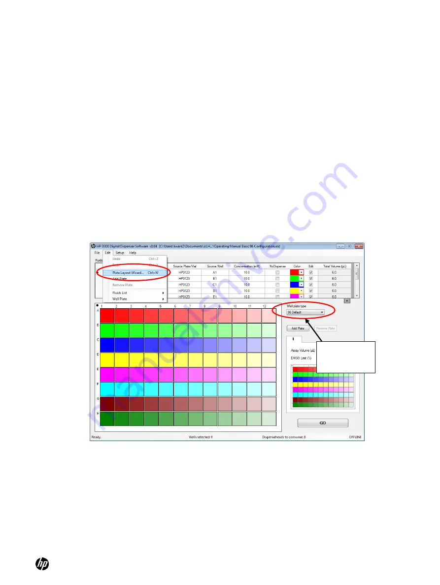
Ensure that the desired well plate type, either 96 or 384, is selected using the Well Plate drop down 
menu prior to starting the Plate Layout Wizard. 

1. 

In the HP D300 Digital Dispenser main operating window, click 

Edit 

and then 

Plate Layout 

Wizard

. The Plate Layout Wizard: Initialization dialog box appears. See 

Figure 5-16

. 

The Plate Layout Wizard can also be accessed by right-clicking on any well in the well plate 
image and then selecting the Wizard option in the Well Plate menu. 


Figure 5-16 

 Click 

Edit

 and then 

Plate Layout Wizard


2. 

If there were existing entries in the Fluids List or fluids in any wells in the well plate, the 
following statement appears in the dialog box: 

Some fluid and/or well data already exists. How would you like to proceed?

‖ 

a. 

Select one of the three options: 


To use the wizard to add fluid to empty wells remaining in the current plate configuration 
only, select 

Leave all existing data alone

.  


To retain the fluids from the Fluids List and design a new plate configuration, select 

Clear the well plate only; leave the fluids alone

.  

Select desired 
well plate type 
here first 

Summary of Contents for Compaq d300 Series

Page 1: ...HP D300 Digital Dispenser Operating Manual ...

Page 2: ...vallis Oregon 97330 All products made in the U S A The information contained herein is subject to change without notice The only warranties for HP products and services are set forth in the express warranty statements accompanying such products and services Nothing herein should be construed as constituting an additional warranty HP shall not be liable for technical or editorial errors or omission...

Page 3: ... 4 Get to know the Options dialog box 16 4 4 1 Options General 17 4 4 2 Options Edit Units 17 4 4 3 Options Edit Fluid Defaults 18 4 4 4 Options Edit Assay Defaults 19 4 4 5 Options Plate Jitter 19 4 4 6 Options Report 20 4 5 Plate dispense procedure 21 4 5 1 Initiate plate dispense 21 4 5 2 Scan and load the well plates 22 4 5 3 Load a Dispensehead Cassette 22 4 5 4 Load fluid into the Dispensehe...

Page 4: ...d error messages 6 1 Troubleshooting 58 6 1 1 Problems with software 58 6 1 2 Computer issues 58 6 1 3 Unable to home stage 59 6 1 4 Check the A1 location 59 6 1 5 A1 alignment procedure 59 6 1 6 Check the fuses and replace if necessary 61 6 2 Error messages 64 Appendix A HP D300 Digital Dispenser software basics 70 Appendix B Glossary 71 Appendix C Quick Start Guide 72 Appendix D Revision History...

Page 5: ...er is intended to be used in the lab environment for drug discovery purposes with small molecules in DMSO 1 Dispensehead Cassette 2 Pogo mechanism 3 Pogo block 4 Source plate holder 5 Motorized stage and destination plate holder 6 Destination plate 7 Deck 8 Power indicator light HP logo 9 Dispenser USB connection 10 Power switch 11 PC with D300 software Rear view Rear view 7 9 11 10 4 3 8 1 5 6 2 ...

Page 6: ...space Display 1024 x 768 256 colors minimum USB ports 1 1 2 Software Microsoft Windows 7 Vista or XP Microsoft NET Framework 3 5 NET 3 5 is included with Windows 7 NET 3 5 is available for Windows XP and Vista www microsoft com Microsoft Excel 2003 or later Adobe Acrobat Reader www adobe com downloads Do not adjust text size in Windows use 100 only 1 1 3 Environmental operating conditions Temperat...

Page 7: ...General safety rules Place the dispenser on a work surface that supports all four feet securely Plug the dispenser into a standard grounded electrical outlet Note the power requirement 120V in North America or 230V in Europe listed on the back label of the dispenser Avoid the moving parts of the dispenser during operation 2 2 Personal protective equipment The HP D300 Digital Dispenser dispenses ch...

Page 8: ...2A 250V fuses contained in the power inlet module at the rear of the dispenser 2 7 Electrical emissions safety The HP D300 Digital Dispenser has passed an FCC EMC test for electrical emissions safety This device complies with part 15 of the FCC Rules Operation is subject to the following two conditions 1 This device may not cause harmful interference and 2 this device must accept any interference ...

Page 9: ...ergonomic risks associated with the use of the dispenser consider the following work area design ideas Place the dispenser on a work bench at a height that allows for proper visual and physical access for operators Having the dispenser too high can lead to greater shoulder elevation when pipetting into the Dispensehead and having the dispenser too low can lead to increased neck and back flexion If...

Page 10: ...penser that come into contact with chemicals 1 Turn off the dispenser as instructed in the Turn off the HP D300 Digital Dispenser section of this document 2 Remove any unused Dispensehead Cassettes from the Dispenser CAUTION Exposing unused Dispensehead Cassettes to cleaning fluids may compromise their performance 3 Spray a cleaning solution such as a bleach or a 70 ethanol solution onto a fabric ...

Page 11: ...nd remove the four pieces of the shipping bracket 2 Connect the separately packaged power cord to the rear of the dispenser See Figure 4 3 3 Plug the other end of the power cord into the appropriate power outlet See Get started 4 Turn the dispenser on using the main power switch adjacent to the power cord connection on the rear of the Dispenser Press the l on the switch to turn the dispenser on Se...

Page 12: ...0 Digital Dispenser software is started Figure 4 5 Laptop computer showing the HP D300 Digital Dispenser software logo 4 2 Get familiar with the software Every time the software starts if the computer is connected to a Dispenser the computer checks the Dispenser USB communication verifies that the dispenser components are operational and moves the stage and the pogo mechanism to their home positio...

Page 13: ...erating Manual is accessible two different ways either by opening the pdf file in the C Program Files HP D300 directory or by clicking on Help Operating Manual from the main operating window as shown in Figure 4 7 Figure 4 7 Help menu and Help About Window 2 Note that the About window also provides access to the License information and to the Tecan FTP site that always contains the latest version ...

Page 14: ...Concentration mode was selected in the Options Edit Units See Options Edit Units for how to set Volume or Concentration mode TIP If the Set Volume or Set Concentration option is grayed out the fluids table is empty so follow step 4 above to add a fluid to the fluid table 7 Now that you have set up some wells place the cursor over a colored well and observe the information that appears in the well ...

Page 15: ...but it is not necessary that the originating table contain all of the columns that the Fluids List contains Once you have pasted information into the Fluids List if certain cells such as those in the Concentration column do not contain the proper numerical data then default values will be used for those cells TIP Paste information from another file into the Fluids List just as you would in any oth...

Page 16: ...o know the Options dialog box At the HP D300 Digital Dispenser main operating window click Setup and then Options to open the Options dialog box Figure 4 10 Click Setup and then Options to open the Options dialog box Click here to view the entire fluids list If necessary enter the new fluid name source plate source well and concentration here NoDispense check box Edit check box ...

Page 17: ... is displayed when you move the mouse over the well plate image on the main operating window Note that when Show both requested volume and dispensed volumes concentrations is selected the format of the pop up is Requested Dispensed as shown in Figure 4 11 such that the requested volumes and concentrations are shown first and the dispensed volumes and concentrations are shown next enclosed in brack...

Page 18: ...Defaults In the Options dialog box click Edit and then Fluid Defaults to open the Edit Fluid Defaults pane of the Options dialog box Set the default concentration for new fluids and specify whether default fluids will be dispensed See Figure 4 13 Figure 4 13 Edit Fluid Defaults pane of the Options dialog box ...

Page 19: ... for example if you are dispensing into wells containing cells Select Jitter the plate while dispensing into each well to shake the destination plate during the dispense When this option is chosen shaking only above a specified volume may be entered Typically only dispense volumes greater than 100nL have a deleterious effect on plated cells Additionally Jitter the plate after dispensing from each ...

Page 20: ...to view the report after the run Select Automatically save the report after every run to save Report files and Only save if the run was successful to omit reports for aborted runs You may also choose to use the default report naming convention by selecting Use HP D300_configurationame_date_time as the file name and enter the Report File Path where these reports should be saved or if this option is...

Page 21: ... dialog box 4 5 Plate dispense procedure 4 5 1 Initiate plate dispense After selecting the desired plate configuration and verifying the options click the GO button in the lower right corner of the main operating window See Figure 4 17 Figure 4 17 Main operating window ...

Page 22: ...he plate is completely level and down on the destination plate holder Ensure that the A1 well position is at the top left corner of the destination plate holder 3 Click OK The Load Cassette dialog box appears See Figure 4 20 Figure 4 19 Destination plate holder on the dispenser Figure 4 20 Load Cassette dialog box 4 5 3 Load a Dispensehead Cassette 1 If a Dispensehead Cassette is already in place ...

Page 23: ... illuminates the first Dispensehead on the front of the pogo mechanism 1 Fill a low volume pipette with at least the amount of fluid that is indicated in the Load Fluid dialog box or fill a multipipetter with the appropriate number of fluids in the proper order as shown in the Load Fluids dialog box If a multipipetter is used use the Max Load Volume for all Dispenseheads as shown on the right side...

Page 24: ... fluid which is retained in the Dispensehead after dispense also known as the dead volume The dead volume is dependent upon the amount of fluid loaded into the Dispensehead with greater dispense volumes leading to greater dead volumes NOTE The maximum amount of fluid that can be dispensed from a Dispensehead is 10μL If the total dispense volume of a fluid exceeds 10μL the volume will be split betw...

Page 25: ...fluid that was skipped into that next Dispensehead 3 Load fluid into the Dispensehead position indicated in the Load Fluid dialog box when prompted This Dispensehead will be indicated on the dispenser by an illuminated blue LED See Figure 4 24 WARNING Make sure to load the fluid into the opening on top of the Dispensehead Do NOT depress the pipette plunger to the second blow out stop as this could...

Page 26: ... Load fluid dialog box showing OK All button 7 After the fluids in the currently loaded cassette are dispensed into plate 1 then depending upon the configuration you will be asked to either load a new cassette or a new plate Read the prompt dialog box carefully to determine the next step WARNING For multiplate configurations the D300 software first minimizes the use of dispenseheads so that fluids...

Page 27: ...erated and saved on your computer after the plate dispense operation is completed To change these report settings click Setup then Options and then Report see Options Report If you have chosen not to display the report after each run you can still view data from the most recently completed run by clicking File and then View Report See Figure 4 27 Figure 4 27 Open the Report dialog box by clicking ...

Page 28: ...displayed but information about the fluids and assay volumes can be examined by clicking Fluids or Options in the menu on the left pane To view more information about the dispense operation click the menu options to section of the report you want to view as shown in Figure 4 29 and Figure 4 30 Figure 4 29 Report Fluids sheet ...

Page 29: ...lots use this report file saved in Excel format and add a column of your plate reader data also in this long skinny format Next sort the data by fluid name and concentration in order to process or plot the data by compound and concentration Figure 4 31 Tabulated Results pane Any previously saved report must be viewed in Excel If you have trouble finding the reports the folder that the last report ...

Page 30: ...ow or by clicking on File Exit 2 Turn the Dispenser off using the main power switch on the rear of the dispenser Press down the O of the rocker switch to turn the dispenser off Figure 4 32 On off switch in the ON position 3 Remove any unused Dispensehead Cassettes from the dispenser to avoid contamination from cleaning solutions or the laboratory environment and place them back in the Cassette tra...

Page 31: ... location TIP If desired information can be entered into the Name Source Plate Vial columns by scanning a bar code using a USB bar code reader attached to your computer TIP The Fluids List can also be created by copying and pasting information from an Excel spreadsheet that contains some or all of the fluid data see Get familiar with the software Fluid information in the Excel file must have colum...

Page 32: ...in information about nondispensed fluids in the output report such as for manually or robotically pipetted controls or for blanks 6 To program more than one well plate to be run with the same fluids list select Add Plate To remove the current plate from the current configuration select Remove Plate The Total Volume column values cannot be changed The total volume is the sum of the volume of a flui...

Page 33: ...own in Figure 5 3 the following options are available Select or Deselect All Wells Set Titration see Set concentrations or volumes in wells step 3 Set Concentration or Set Volume see Set concentrations or volumes in wells Step 1 Normalize see Normalize Randomize see Randomize Remove a single fluid and remove all fluids Cut Copy Paste and Paste Special see Use the Paste Special dialog box Clear Wel...

Page 34: ...ells to a constant DMSO level Each fluid is added to the selected wells in a separate programmatic step TIP All of the fluids are shown in the Global View whereas only the fluids marked for editing by selecting the Edit check box in the Fluids List are shown in the well plate image See Figure 5 4 TIP If a well does not contain any fluid it has a dotted outline The dotted outline is also used to de...

Page 35: ...lume is displayed is determined by the setting chosen in the Edit Units pane of the Options dialog box as described in Options Edit Units Select a fluid from the Fluid drop down list box and then type in a concentration or volume that is within the valid range that is stated in the dialog box See Figure 5 5 shown for concentration mode Figure 5 5 Set Concentration dialog box NOTE The lowest possib...

Page 36: ...tion as described in the Randomize section b Select the direction that the titration will be built These choices are not available for random titrations Note that the arrows and shadings of the graphic in this window change as you make different selections to help you understand the options Horizontal This option creates doses from left to right If this box is not checked the default is a vertical...

Page 37: ...ation or volume within the valid concentration range shown in the lower left portion of the Set Titration dialog box g Type the number of replicates at each well concentration or volume level in the Titration Definition area of the dialog box for example type 3 for a triplicate titration NOTE The lowest possible well concentration is determined by the minimum drop volume the fluid concentration an...

Page 38: ... same titration for many different fluids you can use Plate Layout Wizard basics or you can use Paste Special For Paste Special follow these steps 1 Program the initial titration then ensure the wells you want to copy are selected then right click in the well plate image and then click Copy 2 Click in a new well to select the new starting well for the Paste Special then right click and do one of t...

Page 39: ...n can be programmed 1 Ensure that the Fluids List contains the normalization fluid for example a fluid named DMSO 2 Click and drag in the well plate image to select wells to normalize using the control key if you need to select more than one region because some areas of the well plate do not need normalization then right click to open the Edit Well Plate menu and then click Normalize The DMSO Norm...

Page 40: ...note below TIP You may enter a normalization percentage that is less than the valid normalization range however all wells will not be normalized to the same DMSO percentage For example entering 0 1 DMSO normalization will only add DMSO to wells which are less than 0 1 DMSO and any wells which are greater than 0 1 DMSO will have no additional DMSO added to them TIP To ensure proper DMSO normalizati...

Page 41: ...n the CTRL key while clicking on the well 2 Right click to open the Edit Well Plate menu and select Randomize See Figure 5 13 TIP To return to the non randomized ordered plate click Edit and select Undo 3 Only the selected wells are randomized NOTE When DMSO is added to the Fluids List the default concentration is often left at 10mM Since this is not the concentration of neat DMSO this means that ...

Page 42: ...click File and then Save Plate Configuration All plates will be saved in a single file 2 Name the new plate configuration The plate configurations are saved as Excel files They can be edited or even created in Excel but be extremely careful because the format must exactly match what is expected by the HP D300 Digital Dispenser software Figure 5 15 To save the plate configuration click File and Sav...

Page 43: ...gle zone titration1layouts Ensure that the desired well plate type either 96 or 384 is selected using the Well Plate drop down menu prior to starting the Plate Layout Wizard 1 In the HP D300 Digital Dispenser main operating window click Edit and then Plate Layout Wizard The Plate Layout Wizard Initialization dialog box appears See Figure 5 16 The Plate Layout Wizard can also be accessed by right c...

Page 44: ...the NoDispense check box if the fluid should be a no dispense fluid fluids are which are non HP dispensed fluids There needs to be at least one fluid with NoDispense checked in order to reserve rows or columns for controls which are not dispensed by the HP dispenser f To apply a concentration other than the default type the appropriate value in the box at the bottom of the Initialization dialog bo...

Page 45: ...n order to use a different set of concentrations or volumes for one or more fluids a By default designs start with the definition of any titration1 fluids If the desired plate design involves only titration2 fluids click Titration2 none in the left pane or click the Next button to move down the list to the next item Click the Back and Next buttons to go up or down the list as desired Figure 5 18 P...

Page 46: ...in the Titration Type column to define how the points are spaced between the low and the high concentration limits and then type in the number of points If the titration type is not Linear or Log then the spacing between concentration points is fixed so the number of points the high and low limits are adjusted by the software to make a valid titration series when a fixed spacing is specified iv Th...

Page 47: ...e Fluid 3 Left click and drag to designate wells for this NoDispense fluid This Wizard window works slightly differently than the main well plate image in that if you select any wells for this NoDispense fluid by mistake you have to right click those wells to unselect them 4 Repeat steps 2 and 3 for each NoDispense fluid you wish to position Click on Next when finished or select Positioning Titrat...

Page 48: ...titrations which span more than one row or column b Select the Skip every other well check box to generate an interleaved well plate c Once the titrations are positioned properly click Finish to exit the Plate Layout Wizard More complex designs are described in the following section Select a positioning preference here No Dispense control wells denoted with red X ...

Page 49: ...youts The final type of advanced designs are drug drug interaction or synergy experiments where two compounds are placed in the same well for many wells in a set of orthogonal concentrations We call this a titration 2 layout since there are two compounds in each well and is described in Create titration2 layouts two fluids per well All of these advanced functions take advantage of the digital natu...

Page 50: ...entration for the finely spaced region in the Center Points Around box For example the presumed IC50 value might be used A value of 100 nM has been chosen for this example ii Enter the number of points for the finely spaced region in the Number of Points box iii Select the titration type to be used for the set of points by clicking the arrow on the Titration Type drop down list box iv Enter a valu...

Page 51: ...gh µM columns for zones 1 and 3 as shown in Figure 5 24 ii Select the Titration Type for zones 1 and 3 Figure 5 24 Titration1 pane creating a multizone titration1 layout part 2 iii Click on the Remove Zone Overlap button since the three zones have some overlapping concentrations Removing the zone overlap will delete points from the titration which is why the number of points for zones 2 and 3 was ...

Page 52: ... Modified range titrations can only be created with the Wizard if the dispenser is setup to use concentration mode 1 If not already in Concentration mode click Setup Options Units and select the Concentration radio button as described in Options Edit Units 2 To generate a modified range titration1 with a shifted titration range follow steps 1 and 2 in 5 9 1 above and then click Titration1 in the l...

Page 53: ...is shown as 1 µM due to the 1 DMSO limit in a 100 uL assay 8 Click the Use Modification button then note that 100 µM High µM column entry is now red indicating it is outside the new modified range for this fluid Change the value in the High µM column to the upper limit specified by the Valid Concentration Range display in the dialog box 1 µM in this case and the titration is complete Make sure to ...

Page 54: ...indicating that it is outside the valid concentration range 10 Click the Modified Range button The Valid Range Modification dialog box appears 11 Select the Fluid Extension option Figure 5 29 Valid Range Modification dialog box Note that the wizard suggests using an additional fluid at a concentration of 0 1 mM which provides a valid concentration range of 0 00002 µM to 100 µM exactly what is need...

Page 55: ...s unless the Remove points in the high side triangle option is selected as described below 1 To set up a titration2 layout with two fluids per well in a systematic design follow steps 1 and 2 in 5 9 1 above 2 Click Titration2 in the left pane of the Plate Layout Wizard Titrations and Positioning dialog box This opens the Titration2 none in the left pane of the Plate Layout Wizard Titrations and Po...

Page 56: ... Select 1 in the How many titration zones are there drop down list box c Type 0 002 in the Low µM column d Type 100 in the High µM column e Type 12 in the No of Points column to create a 12 point singlet 5 Click the second tab for the second compound and use the same settings as you did for fluid 1 6 If desired select the Remove points in the high side triangle log log check box In looking for add...

Page 57: ...0 Digital Dispenser 57 Figure 5 32 Titration2 pane with remove points in the high side triangle selected Remove points in the high side triangle log log check box Note that the design uses 78 of the 96 wells ...

Page 58: ...ername HP D300 Password HP Tecan This FTP site can also be accessed directly from the HP D300 Digital Dispenser software by clicking on Help About and then selecting the Go There Now link 3 The software is installed in the C Program Files HP D300 directory and the file HP D300 Digital Dispenser Operating Manual pdf needs to be in that same directory in order to be launched from the Help Operating ...

Page 59: ...to test the dispenser to make sure the alignment is correct or if you notice poor CVs or fluids dispensed on the side walls or ribs of the destination plate follow the following procedure to test the alignment and modify it if needed Please use this section only if you are comfortable with resetting computer parameters for instruments such as the HP D300 Digital Dispenser If you are unsure about t...

Page 60: ...on your drawing 3 Wipe the dispensed fluid off of the tape that covers the well plate and replace the plate on the destination well plate holder 4 Click Setup Hardware The Stage Setup dialog box opens Figure 6 2 Stage Setup pane Figure 6 3 Hardware Setup Stage pane Up arrow Y button Right arrow X button Step Size Entry Box Move to This Position Set to Current Position and Set to Fail Safe Values b...

Page 61: ... change selected for the 384 plate offset from the 384 A1 position by the ANSI standard distance difference 10 Click the Save All to ROM button in the lower right hand corner of the stage setup window otherwise your changes will not be saved the next time you start the software 11 Close the Setup Hardware Stage menu by clicking on OK at the bottom of the window or on the X in the upper right corne...

Page 62: ... module See Figure 6 6 and Figure 6 7 Figure 6 6 Flip down the black cover and pry out the red fuse holder Figure 6 7 Fuse holder 3 Carefully pry the fuse out of the holder with the small screwdriver or other tool and look for visible damage The fuse is good if the filament is visibly continuous and unbroken from one end of the fuse to the other See Figure 6 8 and Figure 6 9 Fuse box ...

Page 63: ...gainst the metal connector on the pronged end of the fuse holder In Figure 6 10 the pronged end is up Figure 6 10 Insert the fuse so that one end presses against the metal connector on the pronged end of the fuse holder 5 If the fuse is damaged replace both fuses with a new one If either fuse is damaged both fuses should be replaced Make sure the fuse presses against the metal connector on this en...

Page 64: ...e driver is installed correctly Pogo Error Close the software unplug the USB cable that connects the dispenser to your computer and follow the Insert the CD that was enclosed with the Dispenser instructions Could not access the stage Ensure driver is installed correctly Stage Port Error Close the software unplug the USB cable that connects the dispenser to your computer and follow the Insert the C...

Page 65: ...ckness less than 18mm The following error has occurred FIRSYS Dispense Error Save the configuration close the software and turn the dispenser off Restart the dispenser restart the software and retry the configuration The following error has occurred STAGE Dispense Error Save the configuration close the software and turn the dispenser off Restart the dispenser restart the software and retry the con...

Page 66: ...hanism or the destination plate holder and that the Dispensehead Cassette is seated properly Restart the software if retry fails Unable to home due to possible obstructions Ensure there are none and that the well plate if present is seated properly and then re home Unable to Home Ensure that nothing is obstructing the motion of the destination plate holder and that the Dispensehead Cassette is sea...

Page 67: ...mponents Firing System Startup Error Close the software check the USB connection between the dispenser and your computer turn the dispenser on and restart the software Unable to initialize the following hardware components Pogo Startup Error Close the software check the USB connection between the dispenser and your computer turn the dispenser on and restart the software Unable to initialize the fo...

Page 68: ... is obstructing the motion of the destination plate holder Restart the software if retry fails Unable to open the operating manual HP D300 Digital Dispenser Operating Manual pdf Do you have a PDF reader installed No Manual Found Install Adobe Acrobat Reader if it is not already installed on your computer Ensure that the HP D300 Digital Dispenser Operating Manual pdf file is the same directory as t...

Page 69: ...ispensing this split Invalid Dispensehead number Dispense Error Save the configuration close the software and turn the dispenser off Restart the dispenser restart the software and retry the configuration Unable to start dispensing this split Lost comms Dispense Error Save the configuration close the software and turn the dispenser off Restart the dispenser restart the software and retry the config...

Page 70: ...closes the window and modified settings are not saved Right click Right click after selecting a well or wells in the well plate image to open the Edit Well Plate menu Use this menu to perform fluid related tasks on the selected wells Right click anywhere in the Fluids Table to open the Edit Fluids List menu Selecting wells To select wells for performing operations such as configuring dispense conc...

Page 71: ...ration followed by GO to perform the dispense operations described in the plate configuration Titration A series of different concentrations volumes and doses of a fluid which comprise a titration series or the x axis of a dose response analysis Titrations may be singlets one well per dose doublets 2 replicate wells per dose triplicates etc depending on the entry in the number of replicates text b...

Page 72: ...HP D300 Digital Dispenser 72 Appendix C Quick Start Guide ...

Page 73: ...HP D300 Digital Dispenser 73 ...

Page 74: ...mber 64A009000de780105924 Edition Date Revision A December 1 2011 eCMS 10797 New Document B December 5 2011 eCMS 11125 Edits for SW versions up to 1 03 Quick Start Guide for shipping bracket C March 12 2012 eCMS 14092 Edits for SW version 1 04 primarily multiplate capability ...

Reviews: