background image

8

.

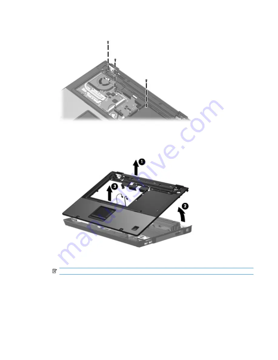
Remove the three Torx T8M2.5×9.0 screws that secure the top cover to the computer.

9

.

Lift the rear edge of the top cover 

(1)

 until it disengages from the base enclosure.

10

.

Swing the rear edge of the top cover 

(2)

 toward you until it rests at an angle.

11

.

Lift the top cover 

(3)

 straight up and remove it.

12

.

If it is necessary to replace the microphone and cable, disconnect the microphone cable 

(1)

 from

the PC Card/audio board assembly and remove it.

NOTE:

The microphone is available in the Cable Kit, spare part number 443887-001.

Component replacement procedures 75

Summary of Contents for Compaq 6715b

Page 1: ...HP Compaq 6715b and 6715s Notebook PC Maintenance and Service Guide ...

Page 2: ...other countries SD Logo is a trademark of its proprietor The information contained herein is subject to change without notice The only warranties for HP products and services are set forth in the express warranty statements accompanying such products and services Nothing herein should be construed as constituting an additional warranty HP shall not be liable for technical or editorial errors or om...

Page 3: ...jor components 17 Plastics Kit 24 Cable Kit 25 Mass storage devices 26 Miscellaneous parts 27 Sequential part number listing 28 4 Removal and replacement procedures Preliminary replacement requirements 34 Tools required 34 Service considerations 34 Plastic parts 34 Cables and connectors 34 Drive handling 35 Grounding guidelines 35 Electrostatic discharge damage 35 Packaging and transporting guidel...

Page 4: ...puter Setup 89 Using Computer Setup 90 Navigating and selecting in Computer Setup 90 Restoring factory settings in Computer Setup 90 Computer Setup menus 91 File menu 91 Security menu 92 Diagnostics menu 93 System Configuration menu 93 6 Specifications Computer specifications 95 15 4 inch WSXGA display specifications 96 15 4 inch WXGA display specifications 97 Hard drive specifications 98 Primary ...

Page 5: ... suggestions 123 Backing up specific files or folders 124 Backing up the entire hard drive 124 Creating recovery points 125 Scheduling backups 125 Performing a recovery 126 Performing a recovery from the recovery discs 126 Performing a recovery from the hard drive 126 Initiating a recovery in Windows 127 Initiating a recovery from the hard drive recovery partition 127 9 Backup and recovery Windows...

Page 6: ...34 External monitor 135 RJ 11 modem 136 RJ 45 network 136 S Video out 137 Universal Serial Bus 137 11 Power cord set requirements Requirements for all countries or regions 138 Requirements for specific countries or regions 139 12 Recycling Battery 140 Display 140 Index 146 vi ...

Page 7: ...ore 1 6 GHz 1 MB L2 cache Mobile AMD Sempron processors 3800 2 2 GHz 256 KB L2 cache 3600 2 0 GHz 256 KB L2 cache 3500 1 8 GHz 512 KB L2 cache 3400 1 8 GHz 256 KB L2 cache Chipset Northbridge RS690T Southbridge SB600 Graphics Unified Memory Architecture UMA integrated with shared video memory Panels 15 4 inch WSXGA with WWAN and WLAN antenna transceivers and cables 15 4 inch WXGA with WWAN and WLA...

Page 8: ... total system memory 2048 MB 2 dual channel 2048 MB total system memory 2048 MB 1 2048 MB total system memory 1024 MB 2 dual channel 1024 MB total system memory 512 MB 2 dual channel 1024 MB total system memory 1024 MB 1 512 MB total system memory 512 MB 1 Hard drives Supports all 9 5 mm 2 5 inch hard drives Serial ATA The following hard drives are available 160 GB 5400 rpm 120 GB 5400 rpm 80 GB 7...

Page 9: ... Integrated Broadcom 5906 10 100 LAN S4 S5 wake on LAN on AC power only Network interface card NIC power down Wireless Integrated wireless options by way of wireless module Wireless local area network WLAN options Broadcom 802 11a b g n Broadcom 802 11a b g Broadcom 802 11b g Option for no WLAN Wireless wide area network WWAN options Evolution data optimized EVDO WWAN module High speed downlink pa...

Page 10: ...t Keyboard pointing devices Spill resistant keyboard with embedded numeric keypad TouchPad and fingerprint reader Spill resistant keyboard with embedded numeric keypad and TouchPad Two way scrolling Windows Vista hardware Start button Power requirements Primary batteries 6 cell 2 55 Ah Li ion battery 55 Whr 6 cell 2 20 Ah Li ion battery 47 Whr Travel batteries 12 cell Li ion battery 8 cell Li ion ...

Page 11: ...ystem board Operating system Preinstalled Windows Vista Home Basic Windows Vista Business 32 64 Free DOS Windows XP Professional Certified SuSe Linux Enterprise Desktop SLED 10 Supported Windows Vista Enterprise Windows XP Professional Serviceability End user replaceable parts AC adapter Hard drive Memory module Optical drive Primary battery WLAN module WWAN module 5 ...

Page 12: ...ut down the computer When the computer is in the Sleep state Windows Vista or in Standby Windows XP press the button briefly to exit Sleep or Standby When the computer is in Hibernation press the button briefly to exit Hibernation If the computer has stopped responding and Windows shutdown procedures are ineffective press and hold the power button for at least 5 seconds to turn off the computer 6 ...

Page 13: ...stablish a wireless connection NOTE A wireless network must be set up in order to establish a wireless connection 5 Presentation button select models only Starts the presentation feature 6 Volume mute button select models only Mutes and restores speaker sound 7 Volume scroll zone select models only Adjusts speaker volume Slide your finger to the left to decrease volume and to the right to increase...

Page 14: ...a function key or the esc key 3 Windows logo key Displays the Windows Start menu 4 Windows applications key Displays a shortcut menu for items beneath the pointer 5 Embedded numeric keypad keys Can be used like the keys on an external numeric keypad 6 Function keys Execute frequently used system functions when pressed in combination with the fn key 8 Chapter 2 External component identification ...

Page 15: ...es are turned off 3 Caps lock light On Caps lock is on 4 Num lock light On Num lock is on or the embedded numeric keypad is enabled 5 Volume mute light select models only Off Computer sound is turned on On Computer sound is turned off 6 Volume down light select models only Blinking The volume scroll zone is being used to decrease speaker volume 7 Volume up light select models only Blinking The vol...

Page 16: ...HP 3D DriveGuard has temporarily parked the internal hard drive TouchPad Item Component Function 1 TouchPad Moves the pointer and selects or activates items on the screen 2 Left TouchPad button Functions like the left button on an external mouse 3 TouchPad scroll zone Scrolls up or down 4 Right TouchPad button Functions like the right button on an external mouse This table describes factory settin...

Page 17: ... full charge capacity Blinking amber A battery that is the only available power source has reached a low battery level When the battery reaches a critical battery level the battery light begins blinking rapidly Off If the computer is plugged into an external power source the light turns off when all batteries in the computer are fully charged If the computer is not plugged into an external power s...

Page 18: ...pillows or thick rugs or clothing to block airflow NOTE The computer fan starts up automatically to cool internal components and prevent overheating It is normal for the internal fan to cycle on and off during routine operation 5 USB ports 2 Connect optional USB devices 6 Audio out headphone jack Produces sound when connected to optional powered stereo speakers headphones ear buds a headset or tel...

Page 19: ... act as a deterrent but it may not prevent the computer from being mishandled or stolen 2 RJ 45 network jack Connects a network cable 3 External monitor port Connects an external VGA monitor or projector 4 S Video out jack Connects an optional S Video device such as a television VCR camcorder overhead projector or video capture card Rear components 13 ...

Page 20: ...d formats Secure Digital SD Memory Card MultiMediaCard MMC Memory Stick MS Memory Stick Pro MSP Memory Stick Duo Adapter xD Picture Card XD 2 USB ports 2 select models only Connect an optional USB device 3 Optical drive Reads an optical disc 4 RJ 11 modem jack Connects a modem cable 14 Chapter 2 External component identification ...

Page 21: ...uch as an adjoining optional printer or a soft surface such as pillows or thick rugs or clothing to block airflow NOTE The computer fan starts up automatically to cool internal components and prevent overheating It is normal for the internal fan to cycle on and off during routine operation 5 Bluetooth module compartment select models only Contains a Bluetooth device 6 Docking connector select mode...

Page 22: ...d parts catalog Serial number location When ordering parts or requesting information provide the computer serial number and model number located on the bottom of the computer 16 Chapter 3 Illustrated parts catalog ...

Page 23: ...Computer major components Computer major components 17 ...

Page 24: ... with WWAN capability 446874 001 15 4 inch WXGA display panel for use only with HP 6715b computer models with WWAN capability 446877 001 15 4 inch WSXGA display panel for use only with HP 6715b computer models without WWAN capability 446873 001 15 4 inch WXGA BrightView display panel for use only with HP 6715b computer models without WWAN capability 446876 001 15 4 inch WXGA display panel for use ...

Page 25: ... 443811 081 France 443811 051 French Canada 443811 121 Germany 443811 041 Greece 443811 DJ1 Hungary 443811 211 International 443811 B31 Iceland 443811 DD1 Israel 443811 BB1 Italy 443811 061 Japan 443811 291 Korea 443811 AD1 Latin America 443811 161 Norway 443811 091 Portugal 443811 131 Russia 443811 251 Saudi Arabia 443811 171 Slovakia 443811 231 Slovenia 443811 BA1 Spain 443811 071 Sweden and Fin...

Page 26: ...spare part information 443905 001 9a PC Card slot bezel 9b Hard drive cover includes 2 captive screws secured by C clips 9c Memory WLAN module compartment cover includes 1 captive screw secured by a C clip 9d Bluetooth module compartment cover includes 1 captive screw secure by a C clip Computer feet 4 large rubber feet 4 small rubber feet not illustrated 10 Processors include thermal material Pro...

Page 27: ...e only with HP Compaq 6715b computer models with WWAN capability includes WWAN module socket 443896 001 For use only with HP Compaq 6715b computer models without WWAN capability does not include WWAN module socket 443898 001 For use only with HP Compaq 6715s computer models 443897 001 15 SIM module slot board for use only with HP Compaq 6715b computer models with WWAN capability 443907 001 16 Spea...

Page 28: ...ucia St Vincent Gren Suriname Swaziland Sweden Switzerland Taiwan Tajikistan Tanzania Togo Tonga Trinidad Tobago Tunisia Turkey Turkmenistan Tuvalu Uganda the United Arab Emirates the United Kingdom Uruguay Uzbekistan Vanuatu Venezuela Vietnam Yemen Zaire Zambia and Zimbabwe 441530 002 For use only in Israel and Japan 441530 291 802 11a b g WLAN modules For use only in Canada the Cayman Islands Gu...

Page 29: ...y Coast Jamaica Jordan Kazakhstan Kenya Kiribati Kuwait Kyrgyzstan Laos Latvia Lebanon Lesotho Liberia Liechtenstein Lithuania Luxembourg Macedonia Madagascar Malawi Malaysia the Maldives Mali Malta the Marshall Islands Martinique Mauritania Mauritius Mexico Micronesia Monaco Mongolia Montenegro Morocco Mozambique Namibia Nauru Nepal the Nether Antilles the Netherlands New Zealand Nicaragua Niger ...

Page 30: ...d drive cover includes 2 captive screws secured by C clips 3 Memory WLAN module compartment cover includes 1 captive screw secured by a C clip 4 Bluetooth module cover includes 1 captive screw secured by a C clip 5 Computer feet 4 large and 4 small rubber feet 24 Chapter 3 Illustrated parts catalog ...

Page 31: ...Cable Kit Item Description Spare part number Cable Kit 443887 001 1 Modem module cable includes RJ 11 connector and cable 2 Microphone includes receiver and cable 3 Bluetooth module cable Cable Kit 25 ...

Page 32: ... 80 GB 7200 rpm 445939 001 80 GB 5400 rpm 443918 001 2 Optical drives include bezel and optical drive bracket DVD RW and CD RW Super Multi Double Layer Combo Drive with LightScribe 443903 001 DVD RW and CD RW Super Multi Double Layer Combo Drive 443904 001 DVD CD RW Combo Drive 443901 001 DVD ROM drive 443902 001 26 Chapter 3 Illustrated parts catalog ...

Page 33: ...ly 246959 061 Japan 246959 291 Korea 246959 AD1 Switzerland 246959 AG1 The United Kingdom 246959 031 The United States 246959 001 Screw Kit Hex HM5 0 9 0 screw lock Phillips PM3 0 3 0 screw Phillips PM2 5 13 0 captive screw Phillips PM2 5 8 0 captive screw Phillips PM2 5 7 0 captive screw Phillips PM2 5 7 0 screw Phillips PM2 5 5 0 screw Phillips PM2 5 3 0 screw Phillips PM2 0 6 0 screw Phillips P...

Page 34: ... Mobile AMD Sempron 3400 1 8 GHz processor for use in all countries and regions except Japan and Asia Pacific 256 KB L2 cache 430872 001 Mobile AMD Sempron 3500 1 8 GHz processor for use in all countries and regions except Japan and Asia Pacific 512 KB L2 cache 430874 001 AMD Turion TL 52 1 6 GHz processor for use in all countries and regions except Japan and Asia Pacific 1 MB L2 cache 430875 001 ...

Page 35: ...Maldives Mali Malta the Marshall Islands Martinique Mauritania Mauritius Mexico Micronesia Monaco Mongolia Montenegro Morocco Mozambique Namibia Nauru Nepal the Nether Antilles the Netherlands New Zealand Nicaragua Niger Nigeria Norway Oman Pakistan Palau Panama Papua New Guinea Paraguay Peru the Philippines Poland Portugal the Republic of Moldova Romania Russia Rwanda Samoa San Marino Sao Tome Pr...

Page 36: ...3811 061 Keyboard for use only in Italy 443811 071 Keyboard for use only in Spain 443811 081 Keyboard for use only in Denmark 443811 091 Keyboard for use only in Norway 443811 121 Keyboard for use only in French Canada 443811 131 Keyboard for use only in Portugal 443811 141 Keyboard for use only in Turkey 443811 161 Keyboard for use only in Latin America 443811 171 Keyboard for use only in Saudi A...

Page 37: ... drive connector board 443821 001 Speakers 443822 001 Top cover for use only with HP Compaq 6715b computer models includes TouchPad TouchPad cable and fingerprint reader 443823 001 Top cover for use only with HP Compaq 6715s computer models includes TouchPad and TouchPad cable 443883 001 Media Card Reader USB connector board for use only with HP Compaq 6715b computer models includes Media Card Rea...

Page 38: ...for use in all countries and regions except Japan and Asia Pacific 1 MB L2 cache 443914 001 Mobile AMD Sempron 3400 1 8 GHz processor for use only in Japan and Asia Pacific countries and regions 256 KB L2 cache 443915 001 Mobile AMD Sempron 3500 1 8 GHz processor for use only in Japan and Asia Pacific countries and regions 512 KB L2 cache 443916 001 Mobile AMD Sempron 3600 2 0 GHz processor for us...

Page 39: ...Kit includes 6 display bezel rubber screw covers 446882 001 Display left and right hinges 446883 001 Display enclosure for use only with HP Compaq 6715b computer models 446884 001 Display panel cable for use only with computer models with WSXGA display panels 446885 001 Display panel cable for use only with computer models with WXGA display panels 446886 001 Wireless Antenna Kit 449137 001 RTC bat...

Page 40: ...assembly and reassembly can damage plastic parts Use care when handling the plastic parts Apply pressure only at the points designated in the maintenance instructions Cables and connectors CAUTION When servicing the computer be sure that cables are placed in their proper locations during the reassembly process Improper cable placement can damage the computer Cables must be handled with extreme car...

Page 41: ...ectrostatic discharge damage Electronic components are sensitive to electrostatic discharge ESD Circuitry design and structure determine the degree of sensitivity Networks built into many integrated circuits provide some protection but in many cases ESD contains enough power to alter device parameters or melt silicon junctions A discharge of static electricity from a finger or other conductor can ...

Page 42: ...floor 12 000 V 5 000 V 3 000 V Motions of bench worker 6 000 v 800 V 400 V Removing DIPS from plastic tube 2 000 V 700 V 400 V Removing DIPS from vinyl tray 11 500 V 4 000 V 2 000 V Removing DIPS from Styrofoam 14 500 V 5 000 V 3 500 V Removing bubble pack from PCB 26 500 V 20 000 V 7 000 V Packing PCBs in foam lined box 21 000 V 11 000 V 5 000 V 36 Chapter 4 Removal and replacement procedures ...

Page 43: ...nd and that proper materials are selected to avoid static charging When grounding is not possible use an ionizer to dissipate electric charges Workstation guidelines Follow these grounding workstation guidelines Cover the workstation with approved static shielding material Use a wrist strap connected to a properly grounded work surface and use properly grounded tools and equipment Use conductive f...

Page 44: ...rips must be worn in contact with the skin The following grounding equipment is recommended to prevent electrostatic damage Antistatic tape Antistatic smocks aprons and sleeve protectors Conductive bins and other assembly or soldering aids Nonconductive foam Conductive tabletop workstations with ground cords of one megohm resistance Static dissipative tables or floor mats with hard ties to the gro...

Page 45: ...y first unplugging the power cord from the AC outlet and then unplugging the AC adapter from the computer 4 Remove the battery see Battery on page 41 5 Remove the real time clock RTC battery see RTC battery on page 59 6 Wait approximately 5 minutes 7 Replace the RTC battery and reassemble the computer 8 Connect AC power to the computer Do not reinsert any batteries at this time 9 Turn on the compu...

Page 46: ... be removed replaced or loosened when servicing the computer Make special note of each screw and screw lock size and location during removal and replacement Serial number Report the computer serial number to HP when requesting information or ordering spare parts The serial number is located on the bottom of the computer 40 Chapter 4 Removal and replacement procedures ...

Page 47: ...nnected to the computer 3 Disconnect the power from the computer by first unplugging the power cord from the AC outlet and then unplugging the AC adapter from the computer Remove the battery 1 Turn the computer upside down on a flat surface with the battery bay toward you 2 Slide the right hand battery release latch 1 to the right and then release the latch 3 Slide and hold the left hand battery r...

Page 48: ...is off or in Hibernation turn the computer on and then shut it down through the operating system 2 Disconnect all external devices connected to the computer 3 Disconnect the power from the computer by first unplugging the power cord from the AC outlet and then unplugging the AC adapter from the computer 4 Remove the battery see Battery on page 41 Remove the SIM module 1 Press in on the SIM module ...

Page 49: ...h the operating system 2 Disconnect all external devices connected to the computer 3 Disconnect the power from the computer by first unplugging the power cord from the AC outlet and then unplugging the AC adapter from the computer 4 Remove the battery see Battery on page 41 Remove the display inverter 1 Turn the computer right side up with the front toward you 2 Open the computer as far as it will...

Page 50: ...the display bezel 3 from the display assembly 7 Release the inverter 1 from the display enclosure as far as the display panel cable and backlight cable allow 8 Disconnect the display panel cable 2 and the backlight cable 3 from the display inverter 9 Remove the display inverter Reverse this procedure to install the display inverter 44 Chapter 4 Removal and replacement procedures ...

Page 51: ...e power cord from the AC outlet and then unplugging the AC adapter from the computer 4 Remove the battery see Battery on page 41 Remove the hard drive 1 Position the computer with the front toward you 2 Loosen the two Phillips PM2 0 5 0 screws 1 that secure the hard drive cover to the computer 3 Lift the left side of the hard drive cover 2 swing it to right and remove the cover NOTE The hard drive...

Page 52: ...rd drive bracket remove the two Phillips PM3 0 3 0 hard drive bracket screws 1 from each side of the hard drive 8 Lift the bracket 2 straight up to remove it from the hard drive Reverse this procedure to reassemble and install the hard drive 46 Chapter 4 Removal and replacement procedures ...

Page 53: ...ific includes Bluetooth module cable 450066 001 Before removing the memory module follow these steps 1 Shut down the computer If you are unsure whether the computer is off or in Hibernation turn the computer on and then shut it down through the operating system 2 Disconnect all external devices connected to the computer 3 Disconnect the power from the computer by first unplugging the power cord fr...

Page 54: ...included in the Plastics Kit spare part number 443905 001 4 Remove the Bluetooth module 1 from the computer 5 Disconnect the Bluetooth module cable 2 from the module 6 Remove the Bluetooth module Reverse this procedure to reassemble and install the Bluetooth module 48 Chapter 4 Removal and replacement procedures ...

Page 55: ...r from the computer by first unplugging the power cord from the AC outlet and then unplugging the AC adapter from the computer 4 Remove the battery see Battery on page 41 Remove the expansion memory module 1 Loosen the Phillips PM2 0 5 0 screw 1 that secures the memory WLAN module compartment cover to the computer 2 Lift the rear edge of the cover 2 swing it toward you and remove the cover NOTE Th...

Page 56: ...way from the socket at an angle NOTE Memory modules are designed with a notch 3 to prevent incorrect installation into the memory module socket Reverse this procedure to install the expansion memory module 50 Chapter 4 Removal and replacement procedures ...

Page 57: ...ay Uzbekistan Vanuatu Venezuela Vietnam Yemen Zaire Zambia and Zimbabwe 441530 002 For use only in Israel and Japan 441530 291 802 11a b g WLAN modules For use only in Canada the Cayman Islands Guam Puerto Rico the United States and the Virgin Islands 441075 001 For use only in Afghanistan Albania Algeria Andorra Angola Antigua Barbuda Argentina Armenia Aruba Australia Austria Azerbaijan the Baham...

Page 58: ...sia Rwanda Samoa San Marino Sao Tome Principe Saudi Arabia Senegal Serbia and Montenegro the Seychelles Sierra Leone Singapore Slovakia Slovenia the Solomon Islands Somalia South Africa South Korea Spain Sri Lanka St Kitts Nevis St Lucia St Vincent Gren Suriname Swaziland Sweden Switzerland Taiwan Tajikistan Tanzania Thailand Togo Tonga Trinidad Tobago Tunisia Turkey Turkmenistan Tuvalu Uganda Ukr...

Page 59: ...e 4 by pulling the module away from the socket at an angle NOTE WLAN modules are designed with a notch 5 to prevent incorrect installation Reverse this procedure to install the WLAN module Component replacement procedures 53 ...

Page 60: ...system 2 Disconnect all external devices connected to the computer 3 Disconnect the power from the computer by first unplugging the power cord from the AC outlet and then unplugging the AC adapter from the computer 4 Remove the battery see Battery on page 41 5 Remove the memory WLAN module compartment cover see Expansion memory module on page 49 Remove the optical drive 1 Position the computer wit...

Page 61: ...l drive bracket remove the two Phillips PM2 0 3 0 screws 1 that secure the bracket to the optical drive 6 Remove the optical drive bracket 2 Reverse this procedure to reassemble and install the optical drive Component replacement procedures 55 ...

Page 62: ... 443811 171 443811 231 443811 BA1 443811 071 443811 B71 443811 BG1 443811 AB1 443811 281 443811 141 443811 031 443811 001 Before removing the keyboard follow these steps 1 Shut down the computer If you are unsure whether the computer is off or in Hibernation turn the computer on and then shut it down through the operating system 2 Disconnect all external devices connected to the computer 3 Disconn...

Page 63: ... the computer as far as possible 5 Slide the four keyboard retention tabs 1 toward you The tabs are located between the esc and f1 keys between the f4 and f5 keys between the f8 and f9 keys and between the f12 and scroll keys 6 Lift the rear edge of the keyboard 2 and swing it toward you until it rests on the palm rest Component replacement procedures 57 ...

Page 64: ...er is off or in Hibernation turn the computer on and then shut it down through the operating system 2 Disconnect all external devices connected to the computer 3 Disconnect the power from the computer by first unplugging the power cord from the AC outlet and then unplugging the AC adapter from the computer 4 Remove the battery see Battery on page 41 5 Remove the memory WLAN module compartment cove...

Page 65: ...efore removing the RTC battery follow these steps 1 Shut down the computer If you are unsure whether the computer is off or in Hibernation turn the computer on and then shut it down through the operating system 2 Disconnect all external devices connected to the computer 3 Disconnect the power from the computer by first unplugging the power cord from the AC outlet and then unplugging the AC adapter...

Page 66: ...N module follow these steps 1 Shut down the computer If you are unsure whether the computer is off or in Hibernation turn the computer on and then shut it down through the operating system 2 Disconnect all external devices connected to the computer 3 Disconnect the power from the computer by first unplugging the power cord from the AC outlet and then unplugging the AC adapter from the computer 4 R...

Page 67: ...N module Aux terminal 2 Remove the two Phillips PM2 5 3 0 screws 2 that secure the WWAN module to the computer The edge of the module opposite the socket rises away from the computer 3 Remove the WWAN module 3 by pulling the module away from the socket at an angle NOTE WWAN modules are designed with a notch 4 to prevent incorrect installation Reverse this procedure to install the WWAN module Compo...

Page 68: ...external devices connected to the computer 3 Disconnect the power from the computer by first unplugging the power cord from the AC outlet and then unplugging the AC adapter from the computer 4 Remove the battery see Battery on page 41 5 Release the keyboard see Keyboard on page 56 Remove the switch cover NOTE Step 1 applies only to HP Compaq 6715b computer models 1 Release the ZIF connector 1 to w...

Page 69: ...d see Keyboard on page 56 6 Remove the switch cover see Switch cover on page 62 Remove the fan 1 Disconnect the fan cable 1 from the system board 2 Loosen the Phillips PM2 5 8 0 screw 2 that secures the fan to the computer 3 Remove the Phillips PM2 5 8 0 screw 3 that secures the fan to the computer 4 Remove the fan 4 Reverse this procedure to install the fan NOTE To properly ventilate the computer...

Page 70: ... and then shut it down through the operating system 2 Disconnect all external devices connected to the computer 3 Disconnect the power from the computer by first unplugging the power cord from the AC outlet and then unplugging the AC adapter from the computer 4 Remove the battery see Battery on page 41 5 Release the keyboard see Keyboard on page 56 6 Remove the switch cover see Switch cover on pag...

Page 71: ...hermal material should be thoroughly cleaned from the surfaces of the heat sink 1 and the processor and system board components 2 each time the heat sink is removed Thermal material is included with all heat sink and processor spare part kits Reverse this procedure to install the heat sink Component replacement procedures 65 ...

Page 72: ...and Asia Pacific countries and regions AMD Turion TL 60 2 0 GHz processor 1 MB L2 cache 443892 001 AMD Turion TL 56 1 8 GHz processor 1 MB L2 cache 443891 001 AMD Turion TL 52 1 6 GHz processor 1 MB L2 cache 443890 001 Mobile AMD Sempron 3500 1 8 GHz processor 512 KB L2 cache 443915 001 Mobile AMD Sempron 3400 1 8 GHz processor 256 KB L2 cache 443914 001 Before removing the processor follow these ...

Page 73: ...erclockwise until you hear a click 2 Lift the processor 2 straight up and remove it NOTE The gold triangle 3 on the processor should be aligned with the triangle 4 embossed on the processor socket when you install the processor Reverse this procedure to install the processor Component replacement procedures 67 ...

Page 74: ...mputer models 443818 001 15 4 inch WXGA display assembly for use only with HP Compaq 6715s computer models 443819 001 Before removing the display assembly follow these steps 1 Shut down the computer If you are unsure whether the computer is off or in Hibernation turn the computer on and then shut it down through the operating system 2 Disconnect all external devices connected to the computer 3 Dis...

Page 75: ...screws 1 that secure the display assembly to the computer NOTE The screw removed from the left hinge secures a ground loop 2 for the display panel cable 4 Position the computer with the rear panel toward you 5 Remove the four Torx T8M2 5 9 0 screws 1 that secure the display assembly to the computer Component replacement procedures 69 ...

Page 76: ...osed section of cable 1 and a metallic grounding sleeve 2 The grounding sleeve must completely cover the exposed section of cable Each cable must be secured inside a space in the copper grounding clip 3 Left to right the cables should be installed in a blue yellow black red sequence Failure to follow these routing instructions can result in degradation of the computer s WLAN and WWAN performance 7...

Page 77: ... top edge NOTE The display bezel rubber screw covers are included in the Display Rubber Kit spare part number 446881 001 The display bezel screws are included in the Display Screw Kit spare part number 446880 001 8 Flex the inside edges of the left and right sides 1 and the top and bottom sides 2 of the display bezel until the bezel disengages from the display enclosure 9 Remove the display bezel ...

Page 78: ... Remove the four Phillips PM2 0 3 0 screws 1 that secure each display hinge to the display panel 13 Remove the display hinges 2 NOTE The left and right display hinges are available using spare part number 446882 001 Reverse this procedure to reassemble and install the display assembly 72 Chapter 4 Removal and replacement procedures ...

Page 79: ...ter 3 Disconnect the power from the computer by first unplugging the power cord from the AC outlet and then unplugging the AC adapter from the computer 4 Remove the battery see Battery on page 41 5 Remove the following components a Hard drive see Hard drive on page 45 b Memory WLAN module compartment cover see Expansion memory module on page 49 c Optical drive see Optical drive on page 54 d Keyboa...

Page 80: ...he TouchPad cable 1 from the system board NOTE Step 6 applies only to HP Compaq 6715b computer models 6 Disconnect the fingerprint reader board cable 2 from the system board 7 Remove the microphone 3 from the clip built into the top cover and remove the microphone cable from the clips built into the top cover 74 Chapter 4 Removal and replacement procedures ...

Page 81: ...the rear edge of the top cover 2 toward you until it rests at an angle 11 Lift the top cover 3 straight up and remove it 12 If it is necessary to replace the microphone and cable disconnect the microphone cable 1 from the PC Card audio board assembly and remove it NOTE The microphone is available in the Cable Kit spare part number 443887 001 Component replacement procedures 75 ...

Page 82: ...ly in Japan and Asia Pacific countries and regions and is also available in the Cable Kit spare part number 443887 001 14 If it is necessary to replace the modem module cable disconnect the cable 1 from the modem module and the system board 2 and remove the modem connector 3 from the clip built into the base enclosure NOTE The modem module cable is available in the Cable Kit spare part number 4438...

Page 83: ... adapter from the computer 4 Remove the battery see Battery on page 41 5 Remove the following components a Hard drive see Hard drive on page 45 b Memory WLAN module compartment cover see Expansion memory module on page 49 c Optical drive see Optical drive on page 54 d Keyboard see Keyboard on page 56 e Switch cover see Switch cover on page 62 f Display assembly see Display assembly on page 68 g To...

Page 84: ...in Hibernation turn the computer on and then shut it down through the operating system 2 Disconnect all external devices connected to the computer 3 Disconnect the power from the computer by first unplugging the power cord from the AC outlet and then unplugging the AC adapter from the computer 4 Remove the battery see Battery on page 41 5 Remove the following components a Hard drive see Hard drive...

Page 85: ...d Reader USB connector board cable 1 from the system board 2 Remove the three Phillips PM2 5 5 0 screws 2 that secure the Media Card Reader USB connector board to the computer 3 Lift the Media Card Reader USB connector board 3 straight up and remove it Reverse this procedure to install the Media Card Reader USB connector board Component replacement procedures 79 ...

Page 86: ...plugging the AC adapter from the computer 4 Remove the battery see Battery on page 41 5 Remove the following components a Hard drive see Hard drive on page 45 b Memory WLAN module compartment cover see Expansion memory module on page 49 c Optical drive see Optical drive on page 54 d Keyboard see Keyboard on page 56 e Switch cover see Switch cover on page 62 f Fan see Fan on page 63 g Heat sink see...

Page 87: ...rews that secure the optical drive connector board 4 Two Phillips PM2 5 3 0 screws that secure the system board NOTE If the computer is equipped with a WWAN module another Phillips PM2 5 5 0 screw 5 that secures the SIM module slot board must be removed 5 Use the right side of the system board 1 immediately behind the optical drive connector to lift the right side of the system board 2 until the r...

Page 88: ... spare part number 443820 001 When replacing the system board be sure that the following components are removed from the defective system board and installed on the replacement system board SIM module see SIM module on page 42 Memory modules see Expansion memory module on page 49 and Internal memory module on page 58 WLAN module see WLAN module on page 51 RTC battery see RTC battery on page 59 WWA...

Page 89: ...PC Card audio board assembly on page 84 Modem module see Modem module on page 85 SIM module slot board see SIM module slot board on page 87 Reverse the preceding procedure to install the system board Component replacement procedures 83 ...

Page 90: ...mputer 4 Remove the battery see Battery on page 41 5 Remove the following components a Hard drive see Hard drive on page 45 b Memory WLAN module compartment cover see Expansion memory module on page 49 c Optical drive see Optical drive on page 54 d Keyboard see Keyboard on page 56 e Switch cover see Switch cover on page 62 f Fan see Fan on page 63 g Heat sink see Heat sink on page 64 h Display ass...

Page 91: ...ugh the operating system 2 Disconnect all external devices connected to the computer 3 Disconnect the power from the computer by first unplugging the power cord from the AC outlet and then unplugging the AC adapter from the computer 4 Remove the battery see Battery on page 41 5 Remove the following components a Hard drive see Hard drive on page 45 b Memory WLAN module compartment cover see Expansi...

Page 92: ...ard audio board assembly on page 84 Remove the modem module 1 Turn the PC Card audio board assembly upside down 2 Remove the two Phillips PM2 5 3 0 screws 1 that secure the modem module to the PC Card audio board assembly 3 Lift the modem module 2 straight up and remove it Reverse this procedure to install the modem module 86 Chapter 4 Removal and replacement procedures ...

Page 93: ...er cord from the AC outlet and then unplugging the AC adapter from the computer 4 Remove the battery see Battery on page 41 5 Remove the following components a Hard drive see Hard drive on page 45 b Memory WLAN module compartment cover see Expansion memory module on page 49 c Optical drive see Optical drive on page 54 d Keyboard see Keyboard on page 56 e Switch cover see Switch cover on page 62 f ...

Page 94: ...ght up and remove it making note of the location of the pins 2 on the SIM module slot board and their alignment with the system board Reverse this procedure to install the SIM module slot board 88 Chapter 4 Removal and replacement procedures ...

Page 95: ...or exchange allowances Starting Computer Setup Computer Setup is a preinstalled ROM based utility that can be used even when the operating system is not working or will not load NOTE Some of the Computer Setup menu items listed in this guide may not be supported by your computer NOTE Pointing devices are not supported in Computer Setup You must use the keyboard to navigate and make selections NOTE...

Page 96: ...ces use the arrow keys to select File Ignore Changes and Exit Then follow the instructions on the screen To save your preferences and exit Computer Setup use the arrow keys to select File Save Changes and Exit Then follow the instructions on the screen Your preferences go into effect when the computer restarts Restoring factory settings in Computer Setup To return all settings in Computer Setup to...

Page 97: ... cache and memory size system ROM video revision and keyboard controller version Restore defaults Replace the configuration settings in Computer Setup with the original factory settings Password settings and security settings are not changed when you restore the factory settings Ignore changes and exit Cancel any changes entered during the current session Then exit and restart the computer Save ch...

Page 98: ...rd readers NOTE You must have an administrator password to change this setting TPM Embedded Security Enable disable support for Trusted Platform Module TPM Embedded Security which protects the computer from unauthorized access to owner functions available in Embedded Security for ProtectTools For more information refer to the ProtectTools software Help NOTE You must have a setup password to change...

Page 99: ...boot order Device configurations Swap the functions of the fn key and left ctrl key Enable disable multiple standard pointing devices at startup To set the computer to support only a single usually nonstandard pointing device at startup select Disable Enable disable USB legacy support When enabled USB legacy support allows the following Use of a USB keyboard mouse and hub in Computer Setup even wh...

Page 100: ...ice Radio Enable disable LAN WLAN Switching When enabled switches to a WLAN when a LAN is either unavailable or disconnected Enable disable Wake on LAN from Off Enable disable the ambient light sensor Port Options Enable disable the serial port Enable disable the parallel port Enable disable the flash media reader Enable disable the USB port CAUTION Disabling the USB port also disables MultiBay de...

Page 101: ...to optical disc 0 C to 35 C 32 F to 95 F Operating writing to optical disc 5 C to 35 C 41 F to 95 F Nonoperating 20 C to 60 C 4 F to 140 F Relative humidity Operating 10 to 90 Nonoperating 5 to 95 Maximum altitude unpressurized Operating 14 7 to 10 1 psia 15 m to 3 048 m 50 ft to 10 000 ft Nonoperating 14 7 to 4 4 psia 15 m to 12 192 m 50 ft to 40 000 ft Shock Operating 125 g 2 ms half sine Nonope...

Page 102: ...A display specifications Metric U S Dimensions Height 20 7 cm 8 15 in Width 33 1 cm 13 03 in Diagonal 39 1 cm 15 39 in Number of colors Up to 16 8 million Contrast ratio 200 1 typical Brightness 180 nits typical Pixel resolution Pitch 0 197 0 197 mm Format 1680 1050 Configuration RGB vertical stripe Backlight CCFT Character display 80 25 Total power consumption 7 0 W Viewing angle 40 horizontal 50...

Page 103: ...er of colors Up to 16 8 million Contrast ratio 200 1 typical Brightness 180 nits typical Pixel resolution Pitch 0 259 0 259 mm Format 1440 900 Configuration RGB vertical stripe Backlight CCFT Character display 80 25 Total power consumption 6 5 W Viewing angle 45 horizontal 15 35 vertical typical 15 4 inch WXGA display specifications 97 ...

Page 104: ...g Single track 3 ms 3 ms 3 ms Average 13 ms 13 ms 13 ms Maximum 24 ms 24 ms 24 ms Logical blocks 312 560 640 234 420 480 156 280 320 Disc rotational speed 5400 rpm 5400 rpm 7200 and 5400 rpm Operating temperature 5 C to 55 C 41 F to 131 F 1 GB 1 billion bytes when referring to hard drive storage capacity Actual accessible capacity is less Actual drive specifications may differ slightly NOTE Certai...

Page 105: ...idth 20 3 cm 7 99 in Depth 5 3 cm 2 09 in Weight 0 34 kg 0 75 lb Energy Voltage 14 4 V Amp hour capacity 2 2 Ah and 2 55 Ah Watt hour capacity 47 Wh and 55Wh Temperature Operating 5 C to 45 C 41 F to 113 F Nonoperating 0 C to 60 C 32 F to 140 F Primary 6 cell Li ion battery specifications 99 ...

Page 106: ... 59 in Disc diameter Standard disc 12 cm 4 72 in Mini disc 8 cm 3 15 in Disc thickness 1 2 mm 0 047 in Track pitch 0 74 µm Access time CD DVD Random 175 ms 230 ms Full stroke 285 ms 335 ms Audio output level Line out 0 7 Vrms Cache buffer 2 MB Data transfer rate 24X CD ROM 3 600 KB sec 8X DVD ROM 10 800 KB sec 24X CD R 3 600 KB sec 16X CD RW 2 400 KB sec 8X DVD R 10 800 KB sec 4X DVD RW 5 400 KB s...

Page 107: ...D RW Center hole diameter 1 5 cm 0 59 in Disc diameter Standard disc 12 cm 4 72 in Mini disc 8 cm 3 15 in Disc thickness 1 2 mm 0 047 in Track pitch 0 74 µm Access time CD DVD Random 110 ms 130 ms Full stroke 210 ms 225 ms Audio output level Line out 0 7 Vrms Cache buffer 2 MB Data transfer rate 24X CD ROM 3 600 KB sec 8X DVD 3 600 KB sec 24X CD R 3 600 KB sec 24X CD RW 3 600 KB sec Transfer mode ...

Page 108: ...12 cm 4 72 in 8 cm 3 15 in Disc thickness 1 2 mm 0 047 in Track pitch 0 74 µm Access time CD DVD Random 100 ms 125 ms Full stroke 175 ms 225 ms Audio output level Line out 0 7 Vrms Cache buffer 512 KB Data transfer rate CD R 24X 3600 KB s 150 KB s at 1X CD rate CD RW 10X 1500 KB s 150 KB s at 1X CD rate CD ROM 24X 3600 KB s 150 KB s at 1X CD rate DVD 8X 10 800 KB s 1 352 KB s at 1X DVD rate Multiw...

Page 109: ...ion DMA0 Not applicable DMA1 Not applicable DMA2 Not applicable DMA3 Not applicable DMA4 Direct memory access controller DMA5 Available for PC Card DMA6 Not assigned DMA7 Not assigned PC Card controller can use DMA 1 2 or 5 System DMA specifications 103 ...

Page 110: ...ller 24C2 Intel 82852 82855 GM GME Graphic Controller Realtek RTL8139 Family PCI Fast Ethernet Controller IRQ11 Intel USB EHCI controller 24CD Intel USB UHCI controller 24C4 Intel USB UHCI controller 24C7 Intel Pro Wireless 2200BG TI OHCI 1394 host controller TI PCI1410 CardBus controller IRQ12 Synaptics PS 2 TouchPad IRQ13 Numeric data processor IRQ14 Primary IDE channel IRQ15 Secondary IDE chann...

Page 111: ...63 Unused 064 Keyboard controller 065 06F Unused 070 071 NMI enable RTC 072 07F Unused 080 08F DMA page registers 090 091 Unused 092 Port A 093 09F Unused 0A0 0A1 Interrupt controller no 2 I O Address hex System Function shipping configuration 0A2 0BF Unused 0C0 0DF DMA controller no 2 0E0 0EF Unused 0F0 0F1 Coprocessor busy clear reset 0F2 0FF Unused 100 16F Unused 170 177 Secondary fixed disk co...

Page 112: ...70 377 Secondary diskette drive controller 378 37F Parallel port LPT1 default 380 387 Unused 388 38B FM synthesizer OPL3 38C 3AF Unused 3B0 3BB VGA 3BC 3BF Reserved parallel port no EPP support 3C0 3DF VGA 3E0 3E1 PC Card controller in CPU 3E2 3E3 Unused 3E8 3EF Internal modem 3F0 3F7 A diskette controller 3F8 3FF Serial port COM1 default CF8 CFB PCI configuration index register PCIDIVO 1 CFC CFF ...

Page 113: ...0 000CBFFF Video BIOS 160 KB 000C8000 000E7FFF Unused 64 KB 000E8000 000FFFFF System BIOS 15 MB 00100000 00FFFFFF Extended memory 58 MB 04800000 07FFFFFF Super extended memory 58 MB 04800000 07FFFFFF Unused 2 MB 08000000 080FFFFF Video memory direct access 4 GB 08200000 FFFEFFFF Unused 64 KB FFFF0000 FFFFFFFF System BIOS System memory map specifications 107 ...

Page 114: ...ks listed in this section are available in the Screw Kit spare part number 443906 001 and the Display Screw Kit spare part number 446880 001 Torx8 T8M2 5 7 0 screw Color Quantity Length Thread Head diameter Black 2 7 0 mm 2 5 mm 5 0 mm Where used 2 screws that secure the bottom edge of the display bezel to the display assembly 108 Chapter 7 Screw listing ...

Page 115: ...rd drive cover to the computer screws are captured on the cover by C clips 2 One screw that secures the Bluetooth module cover to the computer screw is captured on the cover by a C clip 3 One screw that secures the memory WLAN module compartment cover to the computer screw is captured on the cover by a C clip Phillips PM2 0 5 0 captive screw 109 ...

Page 116: ... Length Thread Head diameter Black 1 13 0 mm 2 5 mm 6 0 mm Where used One screw that secures the hard drive to the computer Phillips PM3 0 3 0 screw Color Quantity Length Thread Head diameter Silver 4 3 0 mm 3 0 mm 5 0 mm 110 Chapter 7 Screw listing ...

Page 117: ...hard drive Phillips PM2 5 3 0 screw Color Quantity Length Thread Head diameter Black 6 3 0 mm 2 5 mm 5 0 mm Where used 2 screws that secure the WLAN module to the computer Where used 2 screws that secure the WWAN module to the computer Phillips PM2 5 3 0 screw 111 ...

Page 118: ... board assembly Torx T8M2 5 9 0 screw Color Quantity Length Thread Head diameter Black 23 9 0 mm 2 5 mm 5 0 mm Where used 1 One screw that secures the optical drive to the computer 2 Four screws that secure the display assembly to the computer 112 Chapter 7 Screw listing ...

Page 119: ...d 2 screws that secure the display assembly to the computer Where used 13 screws that secure the top cover to the computer Where used 3 screws that secure the top cover to the computer Torx T8M2 5 9 0 screw 113 ...

Page 120: ...hillips PM2 0 3 0 screw Color Quantity Length Thread Head diameter Black 10 3 0 mm 2 0 mm 4 5 mm Where used 2 screws that secure the optical drive bracket to the optical drive 114 Chapter 7 Screw listing ...

Page 121: ...y hinges to the display panel Black Phillips PM2 5 8 0 captive screw Color Quantity Length Thread Head diameter Black 3 8 0 mm 2 5 mm 5 0 mm Where used 3 screws that secure the keyboard to the computer Black Phillips PM2 5 8 0 captive screw 115 ...

Page 122: ...Quantity Length Thread Head diameter Silver 1 8 0 mm 2 5 mm 5 0 mm Where used 1 screw that secures the fan to the computer Phillips PM2 5 8 0 screw Color Quantity Length Thread Head diameter Black 1 8 0 mm 2 5 mm 5 0 mm 116 Chapter 7 Screw listing ...

Page 123: ...at secures the fan to the system board Phillips PM2 0 6 0 screw Color Quantity Length Thread Heat width Silver 4 6 0 mm 2 0 mm 4 5 mm Where used 4 screws that secure the heat sink to the computer Phillips PM2 0 6 0 screw 117 ...

Page 124: ... Head diameter Black 8 6 0 mm 2 5 mm 5 0 mm Where used 4 screws that secure the top edge of the display bezel to the display enclosure Where used 4 screws that secure the top edge of the display panel to the display enclosure 118 Chapter 7 Screw listing ...

Page 125: ...Hex HM5 0 9 0 screw lock Color Quantity Length Thread Head diameter Silver 2 9 0 mm 3 0 mm 5 0 mm Where used 2 screw locks that secure the top cover to the computer Hex HM5 0 9 0 screw lock 119 ...

Page 126: ... base enclosure Where used 1 Two screws that secure the system board and PC Card audio board assembly to the base enclosure 2 One screw that secures the system board to the base enclosure 3 Two screws that secure the optical drive connector board to the system board 4 One screw that secures the SIM module slot board to the base enclosure 5 One screw that secures the PC Card audio board assembly to...

Page 127: ...PM2 5 3 0 broad head screw Color Quantity Length Thread Head diameter Silver 2 3 0 mm 2 5 mm 7 0 mm Where used 2 screws that secure the system board to the base enclosure Phillips PM2 5 3 0 broad head screw 121 ...

Page 128: ... not compatible with HP Backup Recovery Manager The computer must be connected to AC power during the process Only one set of the recovery discs can be created per computer Number each disc before inserting it into the optical drive of the computer If necessary you can cancel the disc creation before you have finished creating the recovery discs The next time you select Create a set of recovery di...

Page 129: ...a set of recovery discs using HP Backup Recovery Manager Create system recovery points using HP Backup Recovery Manager and periodically copy them to disc Store personal files in the Documents folder and back up these folders periodically Back up templates stored in their associated programs Save customized settings in a window toolbar or menu bar by taking a screen shot of your settings The scree...

Page 130: ... up the entire hard drive When you perform a complete backup of the hard drive you are saving the full factory image including the Windows operating system software applications and all personal files and folders NOTE A copy of the entire hard drive image can be stored on another hard drive on a network drive or on recovery discs that you create NOTE This process may take over an hour depending on...

Page 131: ...ally NOTE Recovering to an earlier recovery point does not affect data files or e mails created since that recovery point To create a system recovery point 1 Select Start All Programs HP Backup Recovery Backup Recovery Manager 2 Click Next 3 Click Create or manage backups and then click Next 4 Click Create or manage Recovery Points and then click Next 5 Follow the on screen instructions Scheduling...

Page 132: ...overy With HP Backup Recovery Manager you can recover your full factory image if you experience system failure or instability HP Backup Recovery Manager works from a dedicated recovery partition on the hard drive or from recovery discs you create Performing a recovery from the recovery discs To perform a recovery from the recovery discs follow these steps 1 Back up all personal files 2 Insert the ...

Page 133: ...very and then click Next 5 Follow the on screen instructions Initiating a recovery from the hard drive recovery partition To initiate a recovery from the hard drive recovery partition follow these steps 1 Back up all personal files 2 Restart the computer and then press f11 before the Windows operating system loads 3 Click a recovery option and then click Next 4 Follow the on screen instructions Pe...

Page 134: ...ger The computer must be connected to AC power during the process Only one set of the recovery discs can be created per computer Number each disc before inserting it into the optical drive of the computer If necessary you can cancel the disc creation before you have finished creating the recovery discs The next time you select Create factory software recovery CDs or DVDs to recover the system High...

Page 135: ... of recovery discs using HP Backup and Recovery Manager Create system recovery points using HP Backup and Recovery Manager and periodically copy them to disc Store personal files in the My Documents folder and back up these folders periodically Back up templates stored in their associated programs Save customized settings in a window toolbar or menu bar by taking a screen shot of your settings The...

Page 136: ...acking up the entire hard drive When you perform a complete backup of the hard drive you are saving the full factory image including the Windows operating system software applications and all personal files and folders NOTE A copy of the entire hard drive image can be stored on another hard drive on a network drive or on recovery discs that you create NOTE This process may take over an hour depend...

Page 137: ...to an earlier recovery point does not affect data files or e mails created since that recovery point To create a system recovery point 1 Select Start All Programs HP Backup Recovery HP Backup and Recovery Manager 2 Click Next 3 Click Back up to protect system settings and important data files and then click Next 4 Click Create or manage Recovery Points and then click Next 5 Follow the on screen in...

Page 138: ...covery With HP Backup and Recovery Manager you can recover your full factory image if you experience system failure or instability HP Backup and Recovery Manager works from a dedicated recovery partition on the hard drive or from recovery discs you create Performing a recovery from the recovery discs To perform a recovery from the recovery discs follow these steps 1 Back up all personal files 2 In...

Page 139: ...or the entire system and then click Next 5 Follow the on screen instructions Initiating a recovery from the hard drive recovery partition To initiate a recovery from the hard drive recovery partition follow these steps 1 Back up all personal files 2 Restart the computer and then press f11 before the Windows operating system loads 3 Click a recovery option and then click Next 4 Follow the on screen...

Page 140: ...assignments Audio out headphone Pin Signal 1 Audio out left channel 2 Audio out right channel 3 Ground Audio in microphone Pin Signal 1 Audio signal in 2 Audio signal in 3 Ground 134 Chapter 10 Connector pin assignments ...

Page 141: ...d analog 2 Green analog 3 Blue analog 4 Not connected 5 Ground 6 Ground analog 7 Ground analog 8 Ground analog 9 5 VDC 10 Ground 11 Monitor detect 12 DDC 2B data 13 Horizontal sync 14 Vertical sync 15 DDC 2B clock External monitor 135 ...

Page 142: ...odem Pin Signal 1 Unused 2 Tip 3 Ring 4 Unused 5 Unused 6 Unused RJ 45 network Pin Signal 1 Transmit 2 Transmit 3 Receive 4 Unused 5 Unused 6 Receive 7 Unused 8 Unused 136 Chapter 10 Connector pin assignments ...

Page 143: ...VHS color C signal 2 Composite video signal 3 S VHS intensity Y signal 4 S VHS color ground 5 TV CD 6 S VHS intensity ground 7 Composite video ground Universal Serial Bus Pin Signal 1 5 VDC 2 Data 3 Data 4 Ground S Video out 137 ...

Page 144: ...ements listed below are applicable to all countries or regions The length of the power cord set must be at least 1 5 m 5 0 ft and no more than 2 0 m 6 5 ft All power cord sets must be approved by an acceptable accredited agency responsible for evaluation in the country or region where the power cord set will be used The power cord sets must have a minimum current capacity of 10 amps and a nominal ...

Page 145: ...two pole grounding type with a NEMA 5 15P 15 A 125 V or NEMA 6 15P 15 A 250 V configuration 3 The appliance coupler flexible cord and wall plug must bear a T mark and registration number in accordance with the Japanese Dentori Law The flexible cord must be Type VCT or VCTF 3 conductor 1 00 mm conductor size The wall plug must be a two pole grounding type with a Japanese Industrial Standard C8303 7...

Page 146: ...you remove these components handle them carefully NOTE Materials Disposal This HP product contains mercury in the backlight in the display assembly that might require special handling at end of life Disposal of mercury may be regulated because of environmental considerations For disposal or recycling information contact your local authorities or see the Electronic Industries Alliance EIA Web site ...

Page 147: ... covers 1 and screws 2 that secure the display bezel to the display assembly 2 Lift up and out on the left and right inside edges 1 and the top and bottom inside edges 2 of the display bezel until the bezel disengages from the display assembly 3 Remove the display bezel 3 Display 141 ...

Page 148: ...y to the display enclosure 6 Remove the display panel assembly 2 from the display enclosure 7 Turn the display panel assembly upside down 8 Remove all screws that secure the display panel frame to the display panel 9 Use a sharp edged tool to cut the tape 1 that secures the sides of the display panel to the display panel frame 142 Chapter 12 Recycling ...

Page 149: ...the display panel 11 Remove the screws 1 that secure the backlight cover to the display panel 12 Lift the top edge of the backlight cover 2 and swing it outward 13 Remove the backlight cover 14 Turn the display panel right side up Display 143 ...

Page 150: ...rn the display panel upside down WARNING The backlight contains mercury Exercise caution when removing and handling the backlight to avoid damaging this component and causing exposure to the mercury 17 Remove the backlight frame from the display panel 144 Chapter 12 Recycling ...

Page 151: ...e LCD panel 20 Remove the screws 2 that secure the LCD panel to the display rear panel 21 Release the LCD panel 3 from the display rear panel 22 Release the tape 4 that secures the LCD panel to the display rear panel 23 Remove the LCD panel 24 Recycle the LCD panel and backlight Display 145 ...

Page 152: ...onents 15 buttons info 7 PC Card eject 12 power 6 presentation 7 volume mute 7 wireless 7 C Cable Kit contents 25 spare part number 25 31 cables service considerations 34 caps lock light 9 chipset product description 1 CMOS clearing 38 components bottom 15 buttons 6 fingerprint reader 6 front 11 keys 8 left side 12 lights 9 rear 13 right side 14 switches 6 top 6 TouchPad 10 computer feet illustrat...

Page 153: ...3 external media cards product description 3 external monitor port location 13 pin assignments 135 F fan removal 63 spare part number 20 32 63 feet illustrated 24 locations 47 File menu 91 fingerprint reader 7 front components 11 function keys 8 G graphics product description 1 grounding equipment and methods 38 H hard drive location 15 precautions 35 product description 2 removal 45 spare part nu...

Page 154: ...cations 100 101 102 optical drive bracket removal 55 optical drive connector board removal 82 spare part number 21 31 82 P packing guidelines 37 panels product description 1 parallel port mode 93 password clearing 38 passwords 92 PC Card eject button 12 PC Card slot 12 PC Card slot bezel illustrated 24 removal 80 PC Card audio board assembly removal 84 spare part numbers 21 31 84 pin assignments a...

Page 155: ...W Combo Drive 101 DVD RW and CD RW Super Multi Double Layer Combo Drive 100 hard drive 98 I O addresses 105 interrupts 104 memory map 107 optical drive 100 101 102 system DMA 103 startup check 93 static shielding materials 38 stringent security 92 switch cover removal 62 spare part numbers 19 32 62 system backup 124 130 system board removal 80 spare part numbers 21 31 80 System Configuration menu ...

Page 156: ......

Reviews: