HP Chromebook x360 14a-cb0 Series Maintenance And Service Manual Download Page 43

Table 5-7

Heat sink descriptions and part number

Description

Spare part number

Heat sink (includes replacement thermal material)

M59279-001

Before removing the heat sink, follow these steps:

1.

Prepare the computer for disassembly (see 

Preparation for disassembly on page 27

).

2.

Remove the bottom cover (see 

Bottom cover on page 27

).

3.

Disconnect the battery cable from the system board (see 

Battery on page 29

).

4.

Remove the WLAN module (see 

WLAN module on page 31

).

5.

Remove the system board (see 

System board on page 34

).

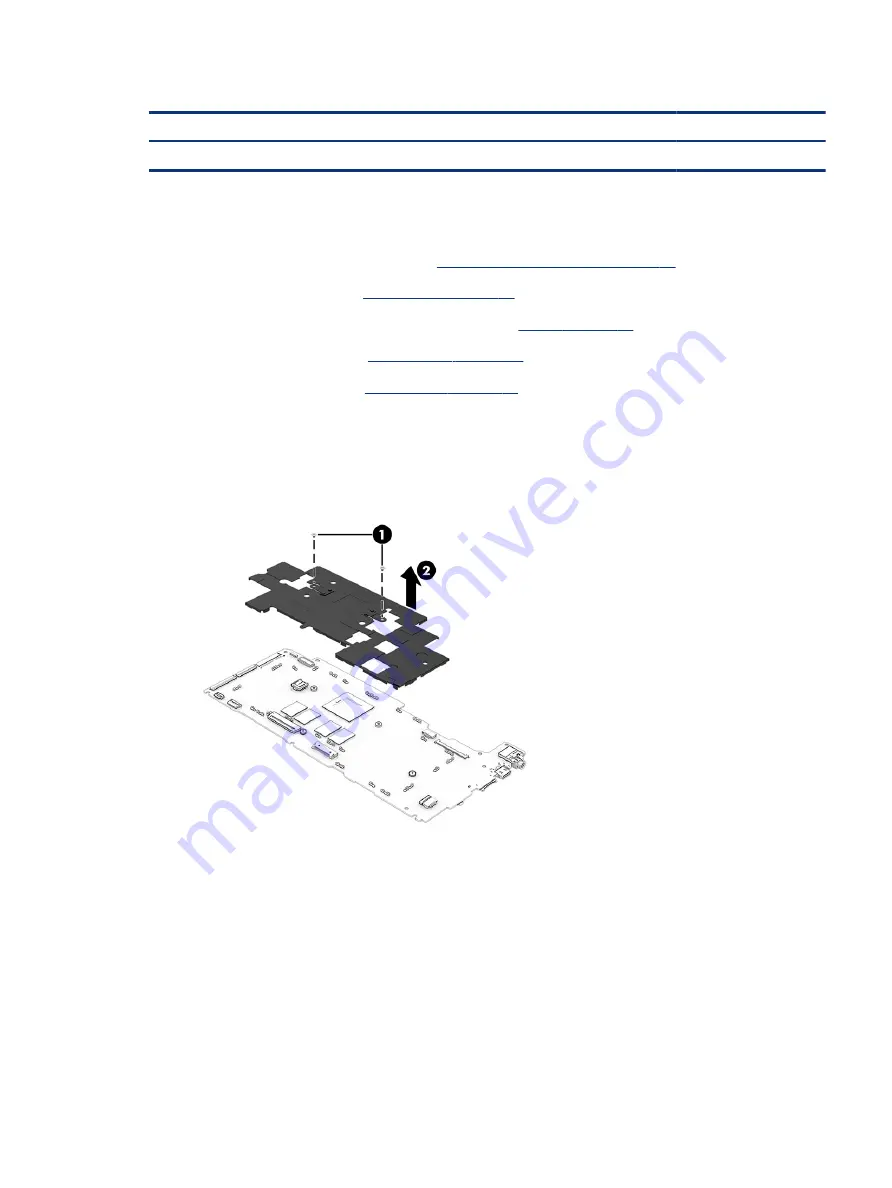
Remove the heat sink:

1.

Remove the two Phillips M2.0 × 3.6 screws (1) that secure the heat sink to the system board.

2.

Remove the heat sink (2).

3.

Thoroughly clean the thermal paste material from the surfaces of the heat sink and the system board 

components each time the heat sink is removed. Replacement thermal material is included with the heat 

sink and system board spare part kits. The following illustration shows the replacement thermal material 

locations.

Thermal paste is used on the processor (1) and the heat sink area (2) that services it.

Heat sink

37

Summary of Contents for Chromebook x360 14a-cb0 Series

Page 1: ...Maintenance and Service Guide SUMMARY This guide provides information about spare parts removal and replacement of parts security backing up and more ...

Page 2: ...press warranty statements accompanying such products and services Nothing herein should be construed as constituting an additional warranty HP shall not be liable for technical or editorial errors or omissions contained herein First Edition June 2021 Document Part Number M73770 001 Product notice This guide describes features that are common to most models Some features may not be available on you...

Page 3: ...ct the computer air vents Use the computer only on a hard flat surface Do not allow another hard surface such as an adjoining optional printer or a soft surface such as pillows or rugs or clothing to block airflow Also do not allow the AC adapter to come into contact with the skin or a soft surface such as pillows or rugs or clothing during operation The computer and the AC adapter comply with the...

Page 4: ...iv Safety warning notice ...

Page 5: ...atic damage to equipment 19 Personal grounding methods and equipment 19 Grounding the work area 20 Recommended materials and equipment 20 Cleaning your computer 21 Enabling HP Easy Clean select products only 21 Removing dirt and debris from your computer 21 Cleaning your computer with a disinfectant 22 Caring for wood veneer select products only 23 Packaging and transporting guidelines 23 Accessin...

Page 6: ...52 Creating recovery media 52 Recovering the Chrome operating system 53 Setting up your computer after a reset or recovery 53 Erase and reformat the recovery media 53 7 Specifications 55 Computer specifications 55 35 6 cm 14 0 in display specifications 56 8 Power cord set requirements 57 Requirements for all countries 57 Requirements for specific countries and regions 57 9 Recycling 61 Index 63 vi...

Page 7: ...d crystal display LCD high definition HD 1366 768 antiglare white light emitting WLED super vertical alignment SVA 45 NTSC eDP 1 2 flat touchscreen display panel with narrow panel typical brightness 250 nits Memory Two onboard non accessible embedded memory module slots supporting up to 8 GB of RAM DDR4 1600 1 2 V dual channel support FBGA96IC Supports the 8 GB 4 2 and 4 GB 4 1 configurations Prim...

Page 8: ...e keyboard in ceramic white and snow white finishes Full size non backlit island style keyboard in jet black finish Touchpad Touchpad in jet black finish Touchpad with image sensor Multitouch gestures enabled Suports precision touchpad Supports Modern Trackpad Gestures Taps enabled as default Power requirements Battery 2 cell 47 Whr HP Long Life AC adapter 45 watt non PFC standard USB Type C strai...

Page 9: ... connector supplying power to the computer and if needed charging the computer battery and Connects a USB device provides high speed data transfer and for select products charges small devices such as a smartphone when the computer is on or in Sleep mode NOTE Use a standard USB Type C charging cable or cable adapter purchased separately when charging a small external device and Connects a display ...

Page 10: ...l powered stereo speakers headphones earbuds a headset or a television audio cable Also connects an optional headset microphone This jack does not support optional standalone microphones WARNING To reduce the risk of personal injury adjust the volume before putting on headphones earbuds or a headset For additional safety information see the Regulatory Safety and Environmental Notices NOTE When a d...

Page 11: ... connectors facing the computer 2 Insert the card into the memory card reader and then press in on the card until it is firmly seated To remove a card Press in on the card and then remove it from the memory card reader 5 Power button When the computer is off press the button briefly to turn on the computer When the computer is in the Sleep state press the button briefly to exit Sleep select produc...

Page 12: ...y depending on the camera hardware and software installed on your product 4 Camera light On The camera is in use Off The camera is turned off by the software The antennas are not visible from the outside of the computer For optimal transmission keep the areas immediately around the antennas free from obstructions For wireless regulatory notices see the section of the Regulatory Safety and Environm...

Page 13: ...omponent and description Component Description Touchpad zone Reads finger gestures to move the pointer or activate items on the screen Speakers The speakers are located on the left and right side of the keyboard Speakers 7 ...

Page 14: ...Table 2 5 Speakers and their description Component Description Speakers 2 Produce sound Special keys Use the illustration and table to locate the special keys 8 Chapter 2 Components ...

Page 15: ...tions Component Description 1 esc key Activates certain computer functions when pressed in combination with other keys such as tab or shift 2 Search key Opens a search box 3 Action keys Execute frequently used system functions Special keys 9 ...

Page 16: ...10 Chapter 2 Components ...

Page 17: ...TE HP continually improves and changes product parts For complete and current information about supported parts for your computer go to http partsurfer hp com select your country or region and then follow the on screen instructions NOTE Details about your computer including model serial number product key and length of warranty are on the service tag at the bottom of your computer Illustrated part...

Page 18: ...nent spare parts are available For spare part information see Display assembly subcomponents on page 15 2 Top cover keyboard with backlight in Pike silver finish with keyboard in jet black finish includes backlight cable and keyboard cable For use in Belgium M59281 A41 For use in Canada M59281 DB1 For use in Denmark Finland and Norway M59281 DH1 For use in France M59281 051 12 Chapter 3 Illustrate...

Page 19: ...M59280 291 For use in the Netherlands M59280 B31 For use in Spain M59280 071 For use in the United States M59280 001 For use in the United Kingdom M59280 031 Top cover keyboard without backlight in Pike silver finish with keyboard in snow white finish includes keyboard cable For use in Belgium M59282 A41 For use in Canada M59282 DB1 For use in Denmark Finland and Norway M59282 DH1 For use in Franc...

Page 20: ... M59276 001 Equipped with 4 GB of system memory and 64 GB of eMMC storage M59275 001 Equipped with 4 GB of system memory and 32 GB of eMMC storage M59274 001 Thermal Pad Kit not illustrated M85773 001 WLAN module not illustrated Intel Wi Fi 6 AX200 ax 2 2 Bluetooth 5 0 MU MIMO M 2 2230 non vPro 160 MHz PCI e USB WW with two 2 antennas L35282 005 Realtek ac 2 2 Bluetooth 5 0 M 2 2230 PCI e USB WW L...

Page 21: ...descriptions and part numbers Item Component Spare part number 1 Display bezel in jet black finish M59258 001 2 Webcam microphone module includes double sided adhesive M59278 001 Display Bezel Adhesive Kit not illustrated M27496 001 3 Display bracket not available as a spare part component 4 Display panel Display assembly subcomponents 15 ...

Page 22: ...ay panel cable M59264 001 10 Webcam microphone module cable includes double sided adhesive M59265 001 11 Display back cover includes left and right wireless antenna cables and transceivers In ceramic white finish M15304 001 In forest teal finish M59257 001 In mineral silver finish M15303 001 Miscellaneous parts To identify the miscellaneous parts use this table Table 3 3 Miscellaneous part descrip...

Page 23: ...work area to prevent damage Plastic parts Using excessive force during disassembly and reassembly can damage plastic parts Cables and connectors Handle cables with extreme care to avoid damage IMPORTANT When servicing the computer be sure that cables are placed in their proper locations during the reassembly process Improper cable placement can damage the computer Apply only the tension required t...

Page 24: ...ctrostatic discharge information A sudden discharge of static electricity from your finger or other conductor can destroy static sensitive devices or microcircuitry Often the spark is neither felt nor heard but damage occurs An electronic device exposed to electrostatic discharge ESD might not appear to be affected at all and can work perfectly throughout a normal cycle The device might function n...

Page 25: ...ansport products in static safe containers such as tubes bags or boxes Protect all electrostatic parts and assemblies with conductive or approved containers or packaging Keep electrostatic sensitive parts in their containers until they arrive at static free stations Place items on a grounded surface before removing them from their container Always be properly grounded when touching a sensitive com...

Page 26: ...ng connectors or test equipment Use fixtures made of static safe materials when fixtures must directly contact dissipative surfaces Keep the work area free of nonconductive materials such as ordinary plastic assembly aids and polystyrene foam Use conductive field service tools such as cutters screwdrivers and vacuums Avoid contact with pins leads or circuitry Recommended materials and equipment HP...

Page 27: ...select the HP Easy Clean tile 2 Now that your device is disabled for a short period see Removing dirt and debris from your computer on page 21 for the recommended steps to clean the high touch external surfaces on your computer After you remove the dirt and debris you can also clean the surfaces with a disinfectant See Cleaning your computer with a disinfectant on page 22 for guidelines to help pr...

Page 28: ...debris from your computer on page 21 Caring for wood veneer select products only on page 23 or both you might also choose to clean the surfaces with a disinfectant A disinfectant that is within HP s cleaning guidelines is an alcohol solution consisting of 70 isopropyl alcohol and 30 water This solution is also known as rubbing alcohol and is sold in most stores Follow these steps when disinfecting...

Page 29: ...with sharp objects or rough surfaces that might scratch the wood See Removing dirt and debris from your computer on page 21 for the recommended steps to clean the high touch external surfaces on your computer After you remove the dirt and debris you can also clean the surfaces with a disinfectant See Cleaning your computer with a disinfectant on page 22 for sanitizing guidelines to help prevent th...

Page 30: ...uter and allow the operating system to open 2 Click the search icon in the taskbar 3 Type Event Viewer and then press enter 4 Select the log from the left panel Details display in the right panel Chrome 1 Go to support google com chrome 2 Search collect Chrome device logs Technical bulletins To locate technical bulletins 1 Go to www hp com 2 Place the cursor over Problem solving to display more op...

Page 31: ...4 3 Support information locations continued Service consideration Path to access information 3 Near the bottom of the window select Notebook PCs and then select your location Accessing support information 25 ...

Page 32: ...26 Chapter 4 Removal and replacement procedures preliminary requirements ...

Page 33: ...nd then follow the on screen instructions You must remove replace or loosen as many as 56 screws when you service the parts described in this chapter Make special note of each screw size and location during removal and replacement Preparation for disassembly To remove and replace computer components use these procedures See Removal and replacement procedures preliminary requirements on page 17 for...

Page 34: ...ear rubber foot strips The rubber screw covers and the rubber foot strips are available using spare part number M15301 001 5 Remove the nine Phillips M2 0 7 6 screws 3 that secure the bottom cover to the computer 6 Insert a nonmarking nonconductive tool 1 into the rear edge of the computer between the bottom cover and the top cover keyboard 7 Swing the rear edge of the bottom cover 2 up and away f...

Page 35: ... 006 Before removing the battery follow these steps 1 Prepare the computer for disassembly see Preparation for disassembly on page 27 2 Remove the bottom cover see Bottom cover on page 27 Remove the battery 1 Disconnect the battery cable 1 from the system board 2 Release the speaker cable from the retention clips 2 and routing channel built into the front edge of the battery 3 Remove the four Phil...

Page 36: ...page 27 3 Disconnect the battery cable from the system board see Battery on page 29 Remove the speakers 1 Disconnect the speaker cable 1 from the system board 2 Release the speaker cable from the retention clips 2 and routing channel built into the front edge of the battery and the top cover keyboard 3 Remove the four Phillips M2 0 5 5 screws 3 that secure the speakers to the computer 4 Remove the...

Page 37: ... in the computer by the governmental agency that regulates wireless devices in your country or region If you replace the module and then receive a warning message remove the module to restore device functionality and then contact technical support Before removing the WLAN module follow these steps 1 Prepare the computer for disassembly see Preparation for disassembly on page 27 2 Remove the bottom...

Page 38: ...na cable connects to the WLAN module 1 Aux terminal 4 If the WLAN antenna is not connected to the terminal on the WLAN module install a protective sleeve on the antenna connector as shown in the following illustration Reverse this procedure to install the WLAN module Connector board cables To remove the connector board cables use this procedure and illustration 32 Chapter 5 Removal and replacement...

Page 39: ...hen disconnect the connector board cables from the system board 2 Release the ZIF connectors 2 to which the connector board cables are connected and then disconnect the connector board cables from the connector board 3 Remove the connector board cables 3 Reverse this procedure to install the connector board cables Connector board To remove the connector board use this procedure and illustration Ta...

Page 40: ...oard to the computer 4 Remove the connector board 4 and cables Reverse this procedure to install the connector board System board To remove the system board use these procedures and illustrations Table 5 6 System board descriptions and part numbers Description Spare part number System board includes an integrated AMD 3015Ce processor graphics subsystem with UMA memory and replacement thermal mater...

Page 41: ...n the replacement system board Remove the system board 1 Disconnect the power adapter cable 1 from the system board 2 Disconnect the webcam microphone module cable 2 from the system board 3 Release the adhesive strip 3 that secures the display panel cable to the system board 4 Disconnect the display panel cable 4 from the system board 5 Disconnect the following cables from the system board Speaker...

Page 42: ...al pad material is included with the system board and top cover keyboard spare part kits The following illustration shows the replacement thermal material locations A thermal pad is used on the system board 1 and on the top cover keyboard 2 Reverse this procedure to install the system board Heat sink To remove the heat sink use these procedures and illustrations 36 Chapter 5 Removal and replacemen...

Page 43: ...e WLAN module on page 31 5 Remove the system board see System board on page 34 Remove the heat sink 1 Remove the two Phillips M2 0 3 6 screws 1 that secure the heat sink to the system board 2 Remove the heat sink 2 3 Thoroughly clean the thermal paste material from the surfaces of the heat sink and the system board components each time the heat sink is removed Replacement thermal material is inclu...

Page 44: ...hese steps 1 Prepare the computer for disassembly see Preparation for disassembly on page 27 2 Remove the bottom cover see Bottom cover on page 27 3 Disconnect the battery cable from the system board see Battery on page 29 4 Remove the WLAN module see WLAN module on page 31 5 Remove the system board see System board on page 34 Remove the power adapter cable 1 Turn the system board upside down with...

Page 45: ... cover on page 27 3 Disconnect the battery cable from the system board see Battery on page 29 Remove the display assembly 1 Remove the WLAN shield 1 The WLAN shield is available using spare part number M33459 001 2 Carefully disconnect the two antenna cables from the WLAN module 2 3 Release the WLAN antenna cables from the retention clip 3 built into the top cover keyboard 4 Disconnect the webcam ...

Page 46: ...top cover keyboard 9 Remove the four Phillips M2 5 5 6 screws that secure the display assembly to the computer 10 Swing the top edge of the display assembly 1 away from the top cover keyboard 40 Chapter 5 Removal and replacement procedures for authorized service provider parts ...

Page 47: ...he inside edges of the left and right sides of the bezel 2 to release them c Flex the inside edge of the top of the bezel 3 to release it d Remove the display bezel 4 The display bezel is available using spare part number M59258 001 13 If you need to remove the display panel a Remove the display bezel b Use tweezers to grasp the pull to release tape 1 that is installed under the left and right sid...

Page 48: ... display back cover with double sided adhesive e Release the display panel cable from the retention clips 2 and routing channel built in to the display back cover f Remove the display hinge plug 3 from the left hinge g Lift the top edge 1 of the display panel until it rests at an angle 42 Chapter 5 Removal and replacement procedures for authorized service provider parts ...

Page 49: ...sembly and M59270 001 35 6 cm 14 0 in LCD HD 1920 1080 antiglare SWVA touchscreen display panel assembly 14 If you need to remove the G sensor module a Remove the display bezel b Remove the display panel c Disconnect the G sensor module from the display panel cable The G sensor module is available using spare part number M59379 001 15 If you need to remove the display panel cable Display assembly ...

Page 50: ...isplay panel f Disconnect the display panel cable 3 cable from the display panel The display panel cable is available using spare part number M59264 001 16 If you need to remove the webcam microphone module a Remove the display bezel b Remove the display panel c Remove the two Phillips M2 0 2 9 screws 1 that secure the display bracket to the display back cover 44 Chapter 5 Removal and replacement ...

Page 51: ...o the display back cover with double sided adhesive h Lift up evenly across the webcam microphone module and detach the module up from the display back cover 4 The webcam microphone module is available using spare part number M59278 001 i Release the ZIF connector 1 to which the webcam microphone module cable is attached and then disconnect the webcam microphone module cable 2 from the webcam micr...

Page 52: ...ws 3 that secure the hinges to the display back cover f Release the hinges 4 by sliding them to the inside of the display back cover and then remove the hinges The hinges are available using spare part number M59266 001 g To remove the hinge covers remove the Phillips M2 0 2 9 screw 1 that secures the hinge cover to the hinge h Remove the hinge cover 2 The hinge covers are available using spare pa...

Page 53: ...ng channel built into the display back cover e Detach the wireless antenna transceivers 2 from the display back cover The wireless antenna transceivers are attached to the display back cover with double sided adhesive f Remove the wireless antennas 3 The antennas are available using spare part number M59256 001 Reverse these procedures to reassemble and replace the display assembly Display assembl...

Page 54: ...ttom cover see Bottom cover on page 27 3 Remove the battery see Battery on page 29 Remove the touchpad cable 1 Release the ZIF connector 1 to which the touchpad cable is connected and then disconnect the touchpad cable from the system board 2 Release the ZIF connector 2 to which the touchpad cable is connected and then disconnect the touchpad cable from the touchpad 3 Remove the touchpad cable 3 R...

Page 55: ...e the touchpad 1 Release the ZIF connector 1 to which the touchpad cable is connected and then disconnect the touchpad cable from the system board 2 Release the clear shielding 2 that covers the top edge of the touchpad 3 Remove the grounding tape 3 that secures the touchpad to the top cover keyboard 4 Remove the six Phillips M2 0 1 5 broad head screws 4 that secure the touchpad and touchpad brack...

Page 56: ...50 Chapter 5 Removal and replacement procedures for authorized service provider parts ...

Page 57: ...tly erases everything on your computer hard drive including your downloaded files If possible back up your files before you reset your computer You might want to reset your computer in the following circumstances You see the message Reset this Chrome device You are having problems with your user profile or settings You have tried restarting your computer and it is still not working properly You wa...

Page 58: ...n on the computer press and hold the esc f3 keys and then press the power button The computer restarts and the screen shows the Chrome OS is missing or damaged screen Installing the Chromebook Recovery Utility The Chromebook Recovery Utility is an app used to recover the original operating system and software programs that were installed at the factory This utility can be installed from the Chrome...

Page 59: ...computer restarts with Chrome OS reinstalled Setting up your computer after a reset or recovery After a reset or recovery is complete perform the initial setup process For details on setting up the computer go to http www support google com Erase and reformat the recovery media During the process of creating recovery media the USB flash drive or SD memory card is formatted for use as a recovery to...

Page 60: ...54 Chapter 6 Backing up resetting and recovering ...

Page 61: ...ns Width 32 55 cm 12 82 in Depth 21 97 cm 8 65 in Height front to back 1 82 cm 0 72 in Weight 1 49 kg 3 29 lb Input power Operating voltage and current 19 5 V dc 2 31 A 45 W 19 5 V dc 3 33 A 65 W 19 5 V dc 4 62 A 90 W 19 5 V dc 7 70 A 150 W 19 5 V dc 10 3 A 200 W Temperature Operating 5 C to 35 C 41 F to 95 F Nonoperating 20 C to 60 C 4 F to 140 F Relative humidity noncondensing Operating 10 to 90...

Page 62: ...ratures 35 6 cm 14 0 in display specifications This section provides specifications for your display Table 7 2 Display specifications Metric U S Active diagonal size 35 6 cm 14 0 in Resolution 1920 1080 FHD 1366 768 HD Surface treatment Antiglare FHD HD panels Brightness 250 nits FHD 45 NTSC panel Viewing angle UWVA SVA Backlight WLED Display panel interface eDP 56 Chapter 7 Specifications ...

Page 63: ...han 2 0 m 6 5 ft All power cord sets must be approved by an acceptable accredited agency responsible for evaluation in the country or region where the power cord set will be used The power cord sets must have a minimum current capacity of 10 A and a nominal voltage rating of 125 V ac or 250 V ac as required by the power system of each country or region The appliance coupler must meet the mechanica...

Page 64: ...wo pole grounding type with a NEMA 5 15P 15 A 125 V ac or NEMA 6 15P 15 A 250 V ac configuration CSA or C UL mark UL file number must be on each element 3 The appliance coupler flexible cord and wall plug must bear a T mark and registration number in accordance with the Japanese Dentori Law The flexible cord must be Type VCTF three conductor 0 75 mm or 1 25 mm conductor size The wall plug must be ...

Page 65: ...7 For 127 V ac the flexible cord must be Type SVT or SJT 3 conductor 18 AWG with plug NEMA 5 15P 15 A 125 V ac with UL and CSA or C UL marks For 240 V ac the flexible cord must be Type H05VV F three conductor 0 75 mm or 1 00 mm conductor size with plug BS 1363 A with BSI or ASTA marks Requirements for specific countries and regions 59 ...

Page 66: ...60 Chapter 8 Power cord set requirements ...

Page 67: ...tery in general household waste Follow the local laws and regulations in your area for battery disposal HP encourages customers to recycle used electronic hardware HP original print cartridges and rechargeable batteries For more information about recycling programs see the HP website at http www hp com recycle Recycling 61 ...

Page 68: ...62 Chapter 9 Recycling ...

Page 69: ...32 spare part numbers 14 32 creating recovery media 52 D display specifications 55 56 display back cover illustrated 16 spare part numbers 16 Display Bezel Adhesive Kit spare part number 15 display bracket illustrated 15 spare part number 15 display hinge plug removal 45 46 spare part number 16 display panel illustrated 16 product description 1 removal 41 spare part numbers 16 43 display panel cab...

Page 70: ... 1 microphone 1 operating system 2 pointing device 2 ports 2 power requirements 2 primary storage 1 processors 1 product name 1 security 2 sensors 2 serviceability 2 solid state drive 1 video 1 wireless 1 product name 1 R recovering 52 recovering Chrome operating system 53 Recovery Utility 52 removal and replacement procedures 27 resetting 51 rubber foot strip illustrated 14 removal 28 spare part ...

Page 71: ... wireless antenna illustrated 16 location 6 removal 47 spare part number 16 47 wireless product description 1 WLAN antenna illustrated 16 location 6 removal 47 spare part number 16 47 WLAN module illustrated 14 removal 31 spare part number 14 spare part numbers 31 WLAN module shield removal 31 39 spare part number 14 31 39 workstation guidelines 17 Index 65 ...

Reviews: