background image


Removal and replacement procedures  27 

4.


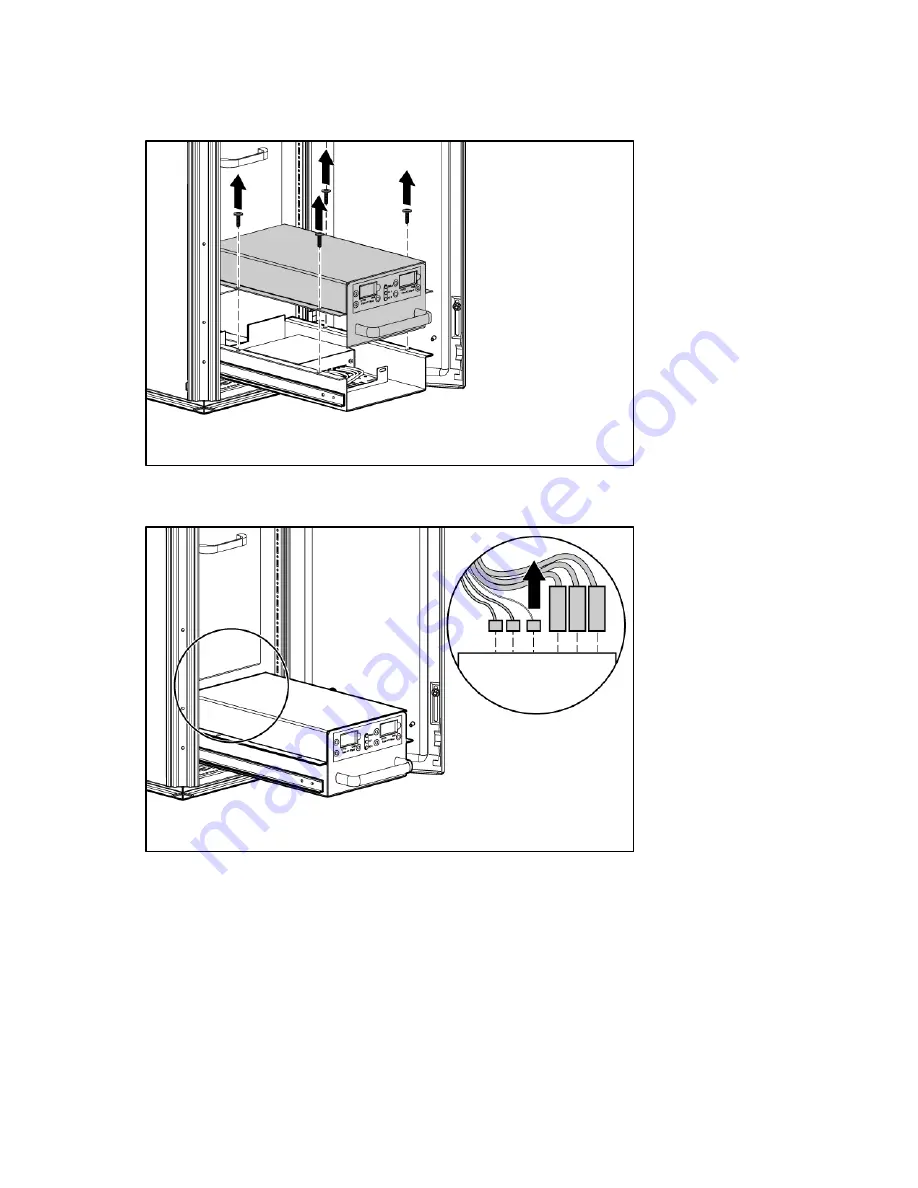
Using a T-25 Torx driver, remove the four Torx screws securing the AC transfer switch chassis to the 

water group controller chassis. The transfer switch chassis cannot be completely removed yet 
because the cables are still connected. 


5.


Disconnect the green and yellow ground bonding wires from the water group controller. 

6.


Disconnect the electrical power cables from the rear of the AC transfer switch. 


Summary of Contents for 403349-003

Page 1: ...HP Modular Cooling System Maintenance and Service Guide Part Number 403349 003 October 2008 Third Edition ...

Page 2: ...services Nothing herein should be construed as constituting an additional warranty HP shall not be liable for technical or editorial errors or omissions contained herein Intended audience This guide is for an experienced service technician HP assumes you are qualified in the servicing of computer equipment and trained in recognizing hazards in products with hazardous energy levels and are familiar...

Page 3: ...e 33 Removing the air deflector plate 33 Replacing the air deflector plate 34 Air sealing plate 34 Removing the air sealing plate 35 Replacing the air sealing plate 36 Automatic door release 38 Removing the front automatic door release 38 Replacing the front automatic door release 39 Removing the rear automatic door release 41 Replacing the rear automatic door release 42 Bottom fan unit 44 Removin...

Page 4: ...00 Water inlet coupling 102 Removing the water inlet coupling 102 Replacing the water inlet coupling 105 Water temperature sensor 107 Removing the water temperature sensor 107 Replacing the water temperature sensor 109 Operation checklist 111 Restoring power to the MCS unit 111 Restoring water flow 112 Technician repair removal and replacement procedures 113 Miscellaneous hardware kit overview 113...

Page 5: ...Diagnostic tools 140 Troubleshooting 141 HP Modular Cooling System troubleshooting 141 Specifications 142 MCS specifications 142 Thermal and air flow performance 143 Environmental specifications 143 HP 10642 G2 Rack specifications 143 Acronyms and abbreviations 144 Index 145 ...

Page 6: ...n will help you over the telephone HP specifies in the materials shipped with a replacement CSR part whether a defective part must be returned to HP In cases where it is required to return the defective part to HP you must ship the defective part back to HP within a defined period of time normally five 5 business days The defective part must be returned with the associated documentation in the pro...

Page 7: ...e vous facturer les coûts de remplacement Dans le cas d une pièce CSR HP supporte l ensemble des frais d expédition et de retour et détermine la société de courses ou le transporteur à utiliser Pour plus d informations sur le programme CSR de HP contactez votre Mainteneur Agrée local Pour plus d informations sur ce programme en Amérique du Nord consultez le site Web HP http www hp com go selfrepai...

Page 8: ...l servizio per i soli componenti HP fornirà gratuitamente le parti di ricambio Per il servizio di garanzia per i soli componenti è obbligatoria la formula CSR che prevede la riparazione da parte del cliente Se il cliente invece richiede la sostituzione ad HP dovrà sostenere le spese di spedizione e di manodopera per il servizio Customer Self Repair HP Produkte enthalten viele CSR Teile Customer Se...

Page 9: ...n muchos componentes que el propio usuario puede reemplazar Customer Self Repair CSR para minimizar el tiempo de reparación y ofrecer una mayor flexibilidad a la hora de realizar sustituciones de componentes defectuosos Si durante la fase de diagnóstico HP o los proveedores o socios de servicio de HP identifica que una reparación puede llevarse a cabo mediante el uso de un componente CSR HP le env...

Page 10: ... HP producten zijn door de klant zelf te repareren waardoor de reparatieduur tot een minimum beperkt kan blijven en de flexibiliteit in het vervangen van defecte onderdelen groter is Deze onderdelen worden CSR onderdelen Customer Self Repair genoemd Als HP of een HP Service Partner bij de diagnose vaststelt dat de reparatie kan worden uitgevoerd met een CSR onderdeel verzendt HP dat onderdeel rech...

Page 11: ...o pelo cliente é obrigatório Se desejar que a HP substitua essas peças serão cobradas as despesas de transporte e mão de obra do serviço Opcional Peças cujo reparo feito pelo cliente é opcional Essas peças também são projetadas para o reparo feito pelo cliente No entanto se desejar que a HP as substitua pode haver ou não a cobrança de taxa adicional dependendo do tipo de serviço de garantia destin...

Page 12: ...garantia apenas para peças Segundo os termos do serviço de garantia apenas para peças a HP fornece as peças de reposição sem cobrar nenhuma taxa No caso desse serviço a substituição de peças CSR é obrigatória Se desejar que a HP substitua essas peças serão cobradas as despesas de transporte e mão de obra do serviço ...

Page 13: ...Customer self repair 13 ...

Page 14: ...Customer self repair 14 ...

Page 15: ...Customer self repair 15 ...

Page 16: ...Customer self repair 16 ...

Page 17: ...ng System are listed in the following table Item Description Spare part number Customer self repair 1 SPS DISPLAY OPERATOR Operator display on page 88 395774 001 Optional2 2 SPS HEAT EXCHANGER Heat exchanger unit HEX with coupler on page 59 395776 001 Optional2 3 SPS MCS MGMT MODULE Management module on page 85 395772 001 Optional2 ...

Page 18: ...t HP to replace these parts you will be charged for the travel and labor costs of this service 2 Optional Parts for which customer self repair is optional These parts are also designed for customer self repair If however you require that HP replace them for you there may or may not be additional charges depending on the type of warranty service designated for your product 3 No Some HP parts are no...

Page 19: ...r parte del usuario es opcional Estos componentes también están diseñados para que puedan ser reparados por el usuario Sin embargo si precisa que HP realice su sustitución puede o no conllevar costes adicionales dependiendo del tipo de servicio de garantía correspondiente al producto 3 No No Algunos componentes no están diseñados para que puedan ser reparados por el usuario Para que el usuario hag...

Page 20: ...ted parts catalog 20 Flow meter repair There are two different flow meter types depending on your MCS model You should be able to discern which type you have based on the label on the rear door of your MCS unit ...

Page 21: ...ou currently have a Type 1 flow meter that you will remove and replace with a Type 2 flow meter For this type of repair you will order the Miscellaneous Hardware Kit and have a trained technician complete your repair or You have a Type 2 flow meter and will remove and replace the flow meter paddle wheel sensor at the top of your flow meter For this type of repair you will order the Flow Meter Padd...

Page 22: ...placement strategies and techniques that might be helpful when attempting to remove and replace spare parts You can access the video on the HP website http www hp com go mcs 1 Select HP Modular Cooling System 2 Under Related Links select HP Support and Drivers 3 Select HP Modular Cooling System 4 Under Resources for Modular Cooling System select Customer self repair steps videos animations 5 Selec...

Page 23: ...h your original MCS unit o Counter hold wrench included with your original MCS unit Heat exchanger unit HEX with ball valves o Adjustable wrench or pipe wrench o T 25 Torx driver HEX coupling o T 25 Torx driver o Water hose fitting wrench included with your original MCS unit o Counter hold wrench included with your original MCS unit o Flathead screwdriver o Utility knife Magnetic solenoid valve o ...

Page 24: ...nt use extreme caution when removing and replacing components that involve water around the electrical wires and unsecured power inlet box There is great risk of electrical shock when water is used near electricity IMPORTANT To reduce the risk of the servers overheating open all of the rack doors of each rack attached to the MCS unit while completing the following procedures in order to increase a...

Page 25: ...ly to disconnect power to the equipment Do not route the power cord where it can be walked on or pinched by items placed against it Pay particular attention to the plug electrical outlet and the point where the cord extends from the storage system 4 Disconnect the two AC power cables from the power connectors labeled Primary and Secondary on the power inlet box 5 Disconnect the network cable from ...

Page 26: ... located at the bottom front of the MCS unit The following tools are required for installation T 25 Torx driver Small Flathead screwdriver Removing the AC transfer switch 1 Power down the MCS unit Powering down the MCS unit on page 24 2 Open the front MCS door 3 Slide the metal AC transfer switch box out toward you on the sliding rails ...

Page 27: ...switch chassis to the water group controller chassis The transfer switch chassis cannot be completely removed yet because the cables are still connected 5 Disconnect the green and yellow ground bonding wires from the water group controller 6 Disconnect the electrical power cables from the rear of the AC transfer switch ...

Page 28: ... starting from the left and moving to the right by pressing the small tab on the bottom of each small cable and pulling it out from the connector After you have disconnected all of the cables the transfer switch chassis is free from restraint and can be removed from the water group controller chassis To replace this component see Replacing the AC transfer switch on page 28 Replacing the AC transfe...

Page 29: ...Connect the electrical power cables from the MCS unit to the AC transfer switch a Connect the three small cables starting from the right and moving to the left by pressing the tab on the bottom of each cable and pushing it into the connector ...

Page 30: ...cable into the connector 3 Using a T 25 Torx driver secure the AC transfer switch chassis to the water group controller chassis by inserting four Torx screws CAUTION To prevent damage to the cables and ensure proper fit of the transfer switch chassis be sure to route all cables through the U shaped opening in the rear of the chassis ...

Page 31: ...he unit The following tools are required for installation T 25 Torx driver Pliers Water hose fitting wrench included with your original MCS unit Counter hold wrench included with your original MCS unit Removing the air bleeder valve 1 Shut off the water flowing into the MCS unit Shutting off the water on page 25 2 Remove the top fan unit Removing the fan unit on page 51 3 Remove the top heat excha...

Page 32: ...leeder valve from the check valve 6 Remove the air bleeder valve from the MCS unit To replace this component see Replacing the air bleeder valve on page 32 Replacing the air bleeder valve 1 Reach into the access panel cut out and align the air bleeder valve to the check valve 2 Firmly hand tighten the air bleeder valve ...

Page 33: ...ore water flow to the MCS unit Restoring water flow on page 112 7 Complete the operation checklist on page 111 Air deflector plate The air deflector plate is not a spare part The removal and replacement instructions for the air deflector plate are provided so that you can access other components No tools are required for this procedure Removing the air deflector plate 1 Loosen the two thumbscrews ...

Page 34: ...ch the ground bonding wires to the air deflector plate 2 Align the two screw holes on the air deflector plate to the two screw holes inside the MCS unit 3 Secure the air deflector plate to the MCS unit by tightening the two thumbscrews in the two screw holes Air sealing plate The air sealing plate is not a spare part The removal and replacement instructions for the air sealing plate are provided s...

Page 35: ... for this procedure Removing the air sealing plate 1 Disconnect the condensation hose from the condensation pump by pressing in the plastic collar quick connect on the condensation pump 2 Loosen the two thumbscrews securing the air sealing plate to the MCS unit ...

Page 36: ...ment procedures 36 3 Slide the air sealing plate out of the MCS unit To replace this component see Replacing the air sealing plate on page 36 Replacing the air sealing plate 1 Slide the air sealing plate into the MCS unit ...

Page 37: ...ocedures 37 2 Secure the air sealing plate to the MCS unit by tightening the two thumbscrews 3 Connect the condensation hose to the condensation pump by inserting it into the plastic collar quick connect on the condensation pump ...

Page 38: ...re located on the front and rear doors of the rack attached to the MCS unit The following tools are required for installation 3 mm Allen wrench T 25 Torx driver Wire cutters Removing the front automatic door release 1 Unplug the electromagnetic lock cable from the panel connector on the MCS unit ...

Page 39: ...e electromagnetic lock and cable from the rack To replace this component see Replacing the front automatic door release on page 39 Replacing the front automatic door release 1 Align the electromagnetic lock to the electromagnetic lock bracket 2 Using an Allen wrench insert and tighten two black cap screws to secure the electromagnetic lock to the electromagnetic lock bracket ...

Page 40: ...Removal and replacement procedures 40 3 Route the magnetic lock cable down through front extension channel across the front of the rack and plug it into the panel connector on the MCS unit ...

Page 41: ... procedures 41 Removing the rear automatic door release 1 Unplug the top and bottom electromagnetic lock cables from the extension lock cable NOTE Be sure to note the location of the electromagnetic brackets prior to removal ...

Page 42: ... an Allen wrench remove the two black cap screws securing each electromagnetic lock to its electromagnetic lock bracket 4 Remove the electromagnetic locks and cables from the rack To replace this component see Replacing the rear automatic door release on page 42 Replacing the rear automatic door release 1 Align the electromagnetic locks to the electromagnetic lock brackets ...

Page 43: ... lock bracket to the rack chassis in the location you noted during removal a Align the electromagnetic lock assembly to the rack chassis in the location you noted during removal b Using a T 25 Torx driver insert and tighten two M5 5 self tapping screws into the inner row of rack holes to secure the electromagnetic lock assembly to the rack chassis 4 Repeat step 3 for the bottom electromagnetic loc...

Page 44: ...nit The removal and replacement instructions for the bottom fan unit are provided so that you can access other components If you are replacing the fan unit see Fan unit on page 50 No tools are required for this procedure Removing the bottom fan unit 1 Open the rear MCS door 2 Using a T 25 Torx driver remove the four Torx screws securing the horizontal shipping bracket to the MCS frame ...

Page 45: ...r shoulders and is heavy and awkward to lift 4 Pull the fan unit out toward you and remove it from the MCS unit To replace this component see Replacing the bottom fan unit on page 45 Replacing the bottom fan unit 1 Align the fan unit to the sliding rails CAUTION The fan unit weighs 16 8 kg 37 lb Use extra caution when removing and replacing the top fan unit because it might be higher than your sho...

Page 46: ...Removal and replacement procedures 46 2 Slide the bottom fan unit inside the MCS unit on the sliding rails 3 Tighten the two thumbscrews to secure the fan unit to the MCS frame ...

Page 47: ...ated at the bottom interior of the MCS unit The following tools are required for installation T 25 Torx driver Phillips screwdriver Removing the condensation pump and sensors 1 Power down the MCS unit Powering down the MCS unit on page 24 2 Remove the bottom fan unit Removing the bottom fan unit on page 44 3 Relocate the power inlet box Relocating the power inlet box on page 93 4 Remove the air se...

Page 48: ...Removal and replacement procedures 48 5 Disconnect the AC power cable from the condensation pump 6 Disconnect the two sensor connections from the condensation pump ...

Page 49: ... and lift the condensation pump from the MCS unit 2 To replace the component see Replacing the condensation pump and sensors on page 49 Replacing the condensation pump and sensors 1 Align the condensation pump thumbscrew to the hole inside the MCS unit 1 and tighten the thumbscrew on the bottom of the condensation pump to secure it to the MCS unit 2 ...

Page 50: ... the air sealing plate Replacing the air sealing plate on page 36 5 Relocate the power inlet box back into position Relocating the power inlet box back into position on page 95 6 Replace the bottom fan unit Replacing the bottom fan unit on page 45 7 Complete the operation checklist on page 111 Fan unit The three fan units are located at the rear of the MCS unit ...

Page 51: ...required for installation T 25 Torx driver Removing the fan unit 1 Open the rear MCS door NOTE The number of horizontal brackets varies depending on the position of the fan unit top middle or bottom 2 Using a T 25 Torx driver remove the four Torx screws securing the horizontal shipping bracket to the MCS frame ...

Page 52: ...han your shoulders and is heavy and awkward to lift 4 Pull the fan unit out toward you and remove it from the MCS unit To replace this component see Replacing the fan unit on page 52 Replacing the fan unit 1 Align the fan unit to the sliding rails CAUTION The fan unit weighs 16 8 kg 37 lb Use extra caution when removing and replacing the top fan unit because it might be higher than your shoulders ...

Page 53: ... Slide the fan unit onto the sliding rails inside the MCS unit 3 Tighten the two thumbscrews to secure the fan unit to the MCS frame NOTE The number of horizontal brackets varies depending on the position of the fan unit top middle or bottom ...

Page 54: ...ottom interior of the MCS unit The following tools are required for installation T 25 Torx driver Wire cutters Water hose fitting wrench included with your original MCS unit Counter hold wrench included with your original MCS Unit Removing the flow meter paddle wheel sensor 1 Power down the MCS unit Powering down the MCS unit on page 24 2 Shut off the water flowing into the MCS unit Shutting off t...

Page 55: ...oving the air deflector plate on page 33 7 Remove the condensation pump and sensors Removing the condensation pump and sensors on page 47 8 Remove the AC transfer switch Removing the AC transfer switch on page 26 9 Remove the plastic lock washer from above the paddle wheel sensor 10 Unscrew the plastic screw cap securing the paddle wheel sensor to the flow meter 11 Lift the paddle wheel sensor up ...

Page 56: ...e paddle wheel sensor and remove the sensor from the MCS unit 13 Disconnect the paddle wheel sensor cable connector labeled X14 from the water group controller and pull the cable completely out of the MCS unit To replace this component see Replacing the flow meter paddle wheel sensor on page 57 ...

Page 57: ...ement procedures 57 Replacing the flow meter paddle wheel sensor 1 Insert the keyed paddle wheel sensor into the top of the flow meter 2 Screw on the plastic screw cap to secure the paddle wheel sensor to the flow meter ...

Page 58: ... group controller 6 Replace the AC transfer switch Replacing the AC transfer switch on page 28 7 Replace the condensation pump and sensors Replacing the condensation pump and sensors on page 49 8 Replace the air deflector plate Replacing the air deflector plate on page 34 9 Replace the bottom fan unit Replacing the bottom fan unit on page 45 10 Restore water flow to the MCS unit Restoring water fl...

Page 59: ...h included with your original MCS unit Removing the heat exchanger unit with couplers NOTE For this procedure remove the fan unit seated directly behind the heat exchanger unit you will remove 1 Remove the fan unit Removing the fan unit on page 51 2 Remove the air deflector plate Removing the air deflector plate on page 33 NOTE The heat exchanger units are deep seated within the MCS unit To access...

Page 60: ...nnector from the heat exchanger unit 4 Using the counter hold wrench to hold the fitting in place and the water hose fitting wrench to loosen the water hose both wrenches are included with your original MCS unit disconnect the In and Out water hoses from the heat exchanger unit ...

Page 61: ...e Torx screws separated according to their thread type and note which thread type came from which hole location on the shipping bracket 8 Remove the two heat exchanger unit shipping brackets a Using a T 25 Torx driver remove the four Torx screws securing the heat exchanger unit shipping brackets to the MCS frame 1 b Using a T 25 Torx driver remove the four Torx screws securing the heat exchanger u...

Page 62: ...ng brackets from the MCS unit 3 CAUTION The heat exchanger unit weighs 23 6 kg 52 lb with the additional weight of the water Use extra caution when removing and replacing the top heat exchanger unit because it might be higher than your shoulders and is heavy and awkward to lift ...

Page 63: ...placing the heat exchanger unit with couplers on page 63 Replacing the heat exchanger unit with couplers CAUTION The heat exchanger unit weighs 23 6 kg 52 lb with the additional weight of the water Use extra caution when removing and replacing the top heat exchanger unit because it might be higher than your shoulders and is heavy and awkward to lift ...

Page 64: ...e and note which thread type came from which hole location on the shipping bracket 2 Install the two heat exchanger unit shipping brackets a Align the heat exchanger unit shipping brackets to the screw holes on the heat exchanger unit and the MCS frame 1 b Using a T 25 Torx driver secure the two heat exchanger unit shipping brackets to the heat exchanger unit by inserting and tightening four Torx ...

Page 65: ...Removal and replacement procedures 65 c Using a T 25 Torx driver secure the two shipping brackets to the MCS frame by inserting and tightening four Torx screws 3 3 Open the rear MCS door ...

Page 66: ...Removal and replacement procedures 66 4 Connect the green and yellow ground bonding wire to the heat exchanger unit 5 Connect the condensation hose to the heat exchanger unit ...

Page 67: ...ect the In and Out water hoses to the heat exchanger unit 7 Connect the temperature sensor connector to the heat exchanger unit 8 Replace the air deflector plate Replacing the air deflector plate on page 34 9 Replace the fan unit Replacing the fan unit on page 52 Complete the operation checklist on page 111 Heat exchanger unit HEX with ball valve The three heat exchanger units are located on the f...

Page 68: ...t seated directly behind the heat exchanger unit you will remove 1 Remove the fan unit Removing the fan unit on page 51 2 Remove the air deflector plate Removing the air deflector plate on page 33 NOTE The heat exchanger units are deep seated within the MCS unit To access the connections described in the following steps extend your arm inside the MCS unit until you come in contact with the appropr...

Page 69: ...lacement procedures 69 4 Disconnect the condensation hose from the HEX unit 5 Disconnect the green and yellow ground bonding wire grounding the HEX unit to the MCS unit 6 Close the two ball valves inside the HEX unit ...

Page 70: ...es 10 Open the front MCS door IMPORTANT Keep the Torx screws separated according to their thread type and note which thread type came from which hole location on the shipping bracket 11 Remove the two HEX unit shipping brackets a Using a T 25 Torx driver remove the four Torx screws securing the HEX unit shipping brackets to the MCS frame 1 b Using a T 25 Torx driver remove the four Torx screws sec...

Page 71: ...ackets from the MCS unit 3 CAUTION The heat exchanger unit weighs 23 6 kg 52 lb with the additional weight of the water Use extra caution when removing and replacing the top heat exchanger unit because it might be higher than your shoulders and is heavy and awkward to lift ...

Page 72: ...r unit with ball valves on page 72 Replacing the heat exchanger unit with ball valves CAUTION The heat exchanger unit weighs 23 6 kg 52 lb with the additional weight of the water Use extra caution when removing and replacing the top heat exchanger unit because it might be higher than your shoulders and is heavy and awkward to lift ...

Page 73: ... thread type and note which thread type came from which hole location on the shipping bracket 2 Install the two HEX unit shipping brackets a Align the HEX unit shipping brackets to the screw holes on the HEX unit and the MCS frame 1 b Using a T 25 Torx driver secure the two HEX unit shipping brackets to the heat exchanger unit by inserting and tightening four Torx screws 2 ...

Page 74: ...Removal and replacement procedures 74 c Using a T 25 Torx driver secure the two HEX unit shipping brackets to the MCS frame by inserting and tightening four Torx screws 3 3 Open the rear MCS door ...

Page 75: ...Removal and replacement procedures 75 4 Connect the green and yellow ground bonding wire to the HEX unit 5 Connect the condensation hose to the HEX unit ...

Page 76: ...nt procedures 76 6 Using an adjustable wrench or a pipe wrench connect the two ball valve hose assemblies to the HEX unit 7 Connect the temperature sensor connector to the HEX unit 8 Open the ball valves inside the HEX unit ...

Page 77: ...r plate Replacing the air deflector plate on page 34 13 Replace the fan unit Replacing the fan unit on page 52 14 Complete the operation checklist on page 111 HEX coupling The three HEX couplings are located at the rear of each HEX unit iinside the MCS unit The following tools are required for installation T 25 Torx driver Water hose fitting wrench included with your original MCS unit Counter hold...

Page 78: ...ng the fan unit on page 51 3 Remove the corresponding air deflector plate Removing the air deflector plate on page 33 4 Disconnect the temperature sensor cable from the heat exchanger unit 5 Slide back the insulation on either the In or Out water hose 6 Using the water hose fitting wrench and the counter hold wrench disconnect either the In or Out water hose from the heat exchanger unit ...

Page 79: ...Removal and replacement procedures 79 7 Using a flathead screwdriver loosen the hose from the HEX coupling 8 Using a utility knife carefully trim approximately 0 64 cm 0 25 in off the water hose ...

Page 80: ... replacement procedures 80 9 Remove the HEX coupling from the water hose To replace this component see Replacing the HEX coupling on page 80 Replacing the HEX coupling 1 Insert the HEX coupling into the water hose ...

Page 81: ...onnect the HEX coupling to the heat exchanger unit 4 Using the water hose fitting wrench and the counter hold wrench reconnect the appropriate In or Out water hose to the heat exchanger unit 5 Confirm that the HEX coupling is fully engaged between the heat exchanger bulkhead and the coupling nut ...

Page 82: ...he fan unit Replacing the fan unit on page 52 10 Restore water flow to the MCS unit Restoring water flow on page 112 11 Complete the operation checklist on page 111 Magnetic solenoid valve The magnetic solenoid valve is a component of the water group located at the bottom interior of the MCS unit The following tools are required for installation T 25 Torx driver Phillips screwdriver Removing the m...

Page 83: ...he valve This process can be difficult If you struggle excessively disconnect the In and Out water hoses on the back of the bottom heat exchanger unit using the counter hold wrench and the water hose fitting wrench 5 On the magnetic solenoid valve release the silver retainer tab 1 and remove the magnetic solenoid from the valve post 2 6 Using a Phillips screwdriver remove the Phillips screw securi...

Page 84: ...valve post This process can be difficult If you struggle excessively disconnect the In and Out water hoses connected to the bottom heat exchanger unit using the counter hold wrench and the water hose fitting wrench 3 Place the magnetic solenoid back on the valve post 1 and press down until the silver retainer tab locks the magnetic solenoid in place on the valve 2 4 Replace the air deflector plate...

Page 85: ...s located on the inside of the front door of the MCS unit No tools are required for this procedure Removing the management module 1 Power down the MCS unit Powering down the MCS unit on page 24 2 Open the front MCS door 3 Disconnect the electrical cables from the management module ...

Page 86: ...the front MCS door To replace this component see Replacing the management module on page 86 Replacing the management module 1 Slide the management module onto the mounting bracket until it locks in place CAUTION To avoid damage to the management module connectors do not allow the cables to pull on the management module connectors ...

Page 87: ...7 2 Connect the electrical cables from the MCS unit to the management module 3 Power on the management module 4 Press and hold the C key for five seconds to confirm the configuration settings 5 Complete the operation checklist on page 111 ...

Page 88: ...allation 8 mm socket Small Flathead screwdriver Removing the operator display 1 Power down the MCS unit Powering down the MCS unit on page 24 2 Open the front MCS door 3 Using an 8 mm socket or wrench remove the three nuts and external star washers securing the operator display rear cover to the back of the front MCS door 4 Remove the operator display rear cover ...

Page 89: ...n 6 Disconnect the connector from the management module 1 and pull the cable up through the cable management hose 2 7 Squeeze the four release tabs on the top and bottom of the operator display 1 and push the operator display from the back to the front through the front MCS door 2 NOTE Cables are removed for clarity ...

Page 90: ...the display button by squeezing the two release tabs on the sides of the display button 1 and pushing the display button from the back to the front through the front MCS door 2 To replace this component see Replacing the operator display on page 91 ...

Page 91: ...e operator display 1 Hold the four release tabs while pushing the operator display from the front to the back through the front MCS door 2 Hold the two release tabs while pushing the display button from the front to the back through the front MCS door ...

Page 92: ...nnect it to the management module connector 2 4 Connect the connector between the operator display and display button 5 Slide any extra slack in the cable lines up into the operator display rear cover and secure by inserting the rubber grommet into the designated notch on the operator display rear cover ...

Page 93: ...inlet box The power inlet box is not a spare part The relocation instructions for the power inlet box are provided so that you can access other components No tools are required for this procedure Relocating the power inlet box 1 Disconnect the green and yellow ground bonding wire grounding the outer support bracket to the MCS unit 2 Remove the outer support bracket a Loosen the four thumbscrews se...

Page 94: ...b Lift the right side of the bracket up at a slant and pull the bracket out of the MCS unit 2 IMPORTANT Do not disconnect any of the internal electrical connections to the power inlet box 3 Pull the power inlet box toward you until it stops ...

Page 95: ... the power inlet box up until the box sits vertically on the left side of the MCS unit To replace this component see Relocating the power inlet box back into position on page 95 Relocating the power inlet box back into position 1 Lower the right side of the power inlet box until it is back into the horizontal position ...

Page 96: ...lace 3 Replace the outer support bracket a Lift the right side of the bracket up at a slant and slide the bracket into the MCS unit b Tighten the four thumbscrews to secure the outer bracket to the MCS unit 4 Connect the green and yellow ground bonding wire to ground the outer support bracket to the MCS unit ...

Page 97: ...ng tools are required for installation T 25 Torx driver Flathead screwdriver 8 mm socket Removing the water group controller 1 Power down the MCS unit Powering down the MCS unit on page 24 2 Remove the AC transfer switch Removing the AC transfer switch on page 26 3 Disconnect the seven electrical cables in the front of the water group controller ...

Page 98: ...rs securing the water group controller bracket to the water group controller chassis 5 Disconnect the two large electrical cables from the back of the water group controller 6 Disconnect the green and yellow grounding wire securing the water group controller to the water group controller chassis ...

Page 99: ... 7 Remove the water group controller mounted on a bracket from the water group controller chassis 8 Slide the water group controller off of the mounting bracket To replace this component see Replacing the water group controller on page 100 ...

Page 100: ...e the water group controller onto the mounting bracket until it locks in place 2 Connect the green and yellow grounding wire to secure the water group controller to the water group controller chassis 3 Connect the two large electrical cables to the back of the water group controller ...

Page 101: ...4 Place the water group controller mounted on the bracket in the water group controller chassis 5 Using an 8 mm socket secure the water group controller bracket to the water group controller chassis by inserting two washers and two 8 mm nuts ...

Page 102: ... Complete the operation checklist on page 111 Water inlet coupling The water inlet coupling is located on the inlet water hose connected to the MCS unit The following tools are required for installation 5 mm Allen wrench Removing the water inlet coupling 1 Power down the MCS unit Powering down the MCS unit on page 24 2 Shut off the water flowing into the MCS unit Shutting off the water on page 25 ...

Page 103: ...dures 103 3 Using a pipe wrench loosen the water inlet coupling and disconnect the water inlet hose from the supply hose 4 Using an Allen wrench remove the four Allen nuts and bolts securing the two brackets to the water inlet hose ...

Page 104: ...inlet hose IMPORTANT Water will drain out of the hose when you remove the coupling Be prepared to catch excess water drainage in a bucket or floor drain 6 Remove the water inlet coupling from the water inlet hose To replace this component see Replacing the water inlet coupling on page 105 ...

Page 105: ... the water inlet coupling 1 Insert the water inlet coupling into the water inlet hose 2 Align the two brackets around the water inlet hose 3 Using an Allen wrench insert and tighten three 40 mm Allen nuts and bolts into three of the four screw holes ...

Page 106: ... one replace the three 40 mm Allen nuts and bolts with the original Allen nuts and bolts until the brackets are firmly compressed around the water inlet hose 6 Using a pipe wrench reconnect the water inlet hose to the supply hose and tighten the water inlet coupling 7 Restore water flow to the MCS unit Restoring water flow on page 112 8 Complete the operation checklist on page 111 ...

Page 107: ...nit Shutting off the water on page 25 3 Remove the bottom fan unit Removing the bottom fan unit on page 44 4 Relocate the power inlet box Relocating the power inlet box on page 93 5 Remove the air sealing plate Removing the air sealing plate on page 35 6 Remove the air deflector plate Removing the air deflector plate on page 33 7 Remove the condensation pump and sensors Removing the condensation p...

Page 108: ...le connected to the water temperature sensor and remove the water temperature probe and cable from the MCS unit 11 Disconnect the appropriate water temperature sensor cable connector from the water group controller and pull the cable completely out of the MCS unit a Disconnect the X12 cable connector if you are repairing the inlet water temperature sensor ...

Page 109: ... repairing the outlet water temperature sensor To replace this component see Replacing the water temperature sensor Replacing the water temperature sensor 1 Insert the new water temperature sensor probe into the appropriate water line 2 Place the cap nut over the water temperature sensor ...

Page 110: ...fer switch on page 28 7 Replace the condensation pump and sensors Replacing the condensation pump and sensors on page 49 8 Replace the air deflector plate Replacing the air deflector plate on page 34 9 Replace the air sealing plate Replacing the air sealing plate on page 36 10 Relocate the power inlet box back into position Relocating the power inlet box back into position on page 95 11 Replace th...

Page 111: ...estoring power to the MCS unit 1 Open the rear MCS door WARNING To reduce the risk of electric shock or damage to the equipment Do not disable the power cord grounding plug The grounding plug is an important safety feature Plug the power cord into a grounded earthed electrical outlet that is easily accessible at all times Unplug the power cord from the power supply to disconnect power to the equip...

Page 112: ...e power connectors on the power inlet box 4 Open the front MCS door 5 Turn on the AC1 breaker on the AC transfer switch 6 Turn on the AC2 breaker on the AC transfer switch Restoring water flow If water was disconnected restore water flow to the MCS unit at the facility side valve ...

Page 113: ...ice contract The customer can order the miscellaneous hardware kit but it will be delivered by a trained HP service technician who will then install the new spare kit by following the removal and replacement instructions in this chapter Miscellaneous hardware kit overview IMPORTANT The following procedures should only be performed by an HP trained technician Description Spare part number Customer ...

Page 114: ...ed with your original MCS unit o Counter hold wrench included with your original MCS unit o 46 mm wrench included in the miscellaneous hardware spare kit Gasket No tools are required for this procedure Magnetic valve diaphragm and spring o T 25 Torx driver o Phillips screwdriver o 8 mm Allen wrench Flow meter The flow meter is a component of the water group located at the bottom interior of the MC...

Page 115: ...hanger unit with couplers on page 59 7 Remove the magnetic solenoid valve Removing the magnetic solenoid valve on page 82 8 Remove the AC transfer switch Removing the AC transfer switch on page 26 9 Using the 46 mm wrench included in the miscellaneous hardware kit loosen the two flow meter union nuts securing the flow meter in place WARNING To reduce the risk of electric shock or damage to the equ...

Page 116: ...Technician repair removal and replacement procedures 116 10 Remove the flow meter from the water line 11 Remove the two fiber gaskets on either side of the water line ...

Page 117: ... meter paddle wheel sensor on page 57 1 Insert the two fiber gaskets on either side of the flow meter IMPORTANT Be sure the arrow on the flow meter is pointing toward the rear of the MCS unit to ensure proper water flow 2 Insert the flow meter back into place on the water line 3 Using the 46 mm wrench included in the miscellaneous hardware kit tighten the two union nuts to secure the flow meter to...

Page 118: ...ecklist on page 111 Magnetic valve The magnetic valve is a component of the water group located at the bottom interior of the MCS unit The following tools are required for installation T 25 Torx driver Phillips screwdriver 8 mm Allen wrench Removing the magnetic valve diaphragm and spring 1 Power down the MCS unit Powering down the MCS unit on page 24 2 Disconnect the main water lines at the quick...

Page 119: ...ng wrench to loosen the water hose both wrenches included with your original MCS unit disconnect the In and Out water hoses from the bottom heat exchanger unit 7 Remove the magnetic solenoid valve Removing the magnetic solenoid valve on page 82 8 Using an 8 mm Allen wrench remove the four socket screws securing the cover of the magnetic valve ...

Page 120: ...s component see Replacing the magnetic valve diaphragm and spring on page 120 Replacing the magnetic valve diaphragm and spring NOTE When you replace the diaphragm inside the magnetic valve be sure to line up the tab of the diaphragm with the indentation of the magnetic valve If it is not aligned properly the cover will not fit correctly which could cause further problems ...

Page 121: ...Technician repair removal and replacement procedures 121 1 Place the diaphragm and spring on the magnetic valve 2 Place the cover on the magnetic valve ...

Page 122: ...nd the water hose fitting wrench to tighten the water hose both wrenches included in your original hardware kit connect the In and Out water hoses to the bottom heat exchanger unit 6 Replace the air deflector plate Replacing the air deflector plate on page 34 7 Relocate the power inlet box back into position Relocating the power inlet box back into position on page 95 8 Replace the bottom fan unit...

Page 123: ...4 Under Resources for HP Modular Cooling System select Customer self repair steps videos animations 5 Select either Heat Exchanger Upgrade or Main Hose Upgrade Upgrading the HEX coupler The HEX couplers are located on the HEX units The following tools are required for installation T 25 Torx driver Small pipe wrench Adjustable wrench Flathead screwdriver Knife Removing the HEX coupler NOTE For this...

Page 124: ...e the three screws on each side of the bottom cover plate and remove the bottom cover plate from the HEX unit 6 Using a flathead screwdriver push in the tabs of the white electrical connector of the temperature sensor and push the connector into the HEX unit ...

Page 125: ...emove it from the barbs 8 Remove the condensation drain hose from both barbs NOTE Depending on the style of the hose barb you might need to remove the hose barb before you remove the quick disconnect If the hose barb is chrome plated remove it before you remove the quick disconnect 9 Using a small pipe wrench and an adjustable wrench remove the quick disconnect by loosening the large nut inside th...

Page 126: ...s 126 10 Using a small pipe wrench loosen the nut attaching the HEX unit copper pipe to each of the ball valve assemblies 11 Using a T 25 Torx driver remove the four screws securing the coupler face plate to the HEX unit ...

Page 127: ...ures 127 12 Remove the coupler faceplate and hose couplers as a single assembly 13 Remove the O ring from each pipe and verify that the pipe is clean To replace this component see Replacing the HEX coupler on page 128 ...

Page 128: ...HEX coupler 1 Install one O ring on to each HEX unit pipe 2 Install each ball valve assembly to the HEX unit tubing positioning the handles down 3 Loosely attach the HEX unit pipe nut to the ball valve assembly barely connecting the threads ...

Page 129: ...faceplate with eight side holes to the ball valve assemblies and slide the faceplate over the ball valve assemblies 5 Align the second faceplate faceplate with round holes to the ball valve assemblies and slide the faceplate over the ball valve assemblies ...

Page 130: ...er install four screws to secure the faceplate NOTE Do not overtighten the fittings The gasket needs only a slight compression to seal the fitting 7 Using a small pipe wrench tighten the fitting that connects the HEX unit copper pipe to the ball valve ...

Page 131: ...llation of the hose barbs and hose clamps to hold the condensation drain line in place while working 9 Connect the condensation drain line between the quick disconnect hose barb and the HEX unit hose barb 10 Insert the white electrical connector into the faceplate and verify that the tabs have locked in place 11 Align the bottom cover plate to the bottom of HEX unit ...

Page 132: ... HEX unit with ball valves that connects the HEX unit to the main water lines The following tools are required for installation Adjustable wrench Knife T 25 Torx driver Removing the HEX hose coupler NOTE For this procedure remove the fan unit seated directly behind the heat exchanger unit you will remove 1 Remove the fan unit Removing the fan unit on page 51 2 Remove the air deflector plate Removi...

Page 133: ...inside the hose union fitting of the hose assembly 3 Hand tighten the union fitting on the assembly aligning the compression washer to the HEX unit NOTE Do not overtighten the fittings The gasket needs only a slight compression to seal the fitting ...

Page 134: ...Upgrading procedures 134 4 Using an adjustable wrench tighten the union fitting 1 8 flat 5 Insert the HEX unit in to the MCS unit ...

Page 135: ... criss cross pattern 7 Cut the hose attached to the old coupler the same length of the replacement hose and insert the hose barb from the HEX unit into the hose 8 Remove the old coupler from the MCS unit 9 Transfer the hose insulation from the old hose assembly to the new ball valve hose assembly attached to the HEX unit 10 Push the insulation back on the cut hose and install a hose clamp ...

Page 136: ...insulation back over the hose and secure with tie wraps 14 Repeat steps 7 through 13 for the other HEX unit hose 15 Open the valves inside the HEX unit and on each hose assembly 16 Install the two HEX unit shipping brackets a Align the HEX unit shipping brackets to the screw holes on the HEX unit and the MCS frame 1 b Using a T 25 Torx driver insert and tighten four Torx screws to the HEX unit 2 ...

Page 137: ...Upgrading procedures 137 c Using a T 25 Torx driver insert and tighten four Torx screws to the MCS frame 3 17 Connect the green and yellow ground bonding wire to the HEX unit ...

Page 138: ... to the HEX unit 19 Connect the temperature sensor cable to the HEX unit 20 Replace the air deflector plate Replacing the air deflector plate on page 34 21 Replace the fan unit Replacing the fan unit on page 52 22 Complete the operation checklist on page 111 ...

Page 139: ... the base assembly Where multiple cooling modules are used the condensate discharge tubes are connected to one another using quick connectors Any condensation that occurs is then removed through this series of connections to the condensation tray When the specified condensation level in the condensation tray is reached a sensor activates a pump that pumps the condensation into the return system A ...

Page 140: ...nger of falling below the dew point increases as water temperature decreases condensation buildup Ensure that the enclosure is sealed on all sides and in particular at the cable inlet condensation formation Diagnostic tools For a complete list of the warning and alarm messages displayed on the operator display and the web interface see the HP Modular Cooling System User Guide included with your or...

Page 141: ...Cooling performance parameters section in the HP Modular Cooling System Web Interface User Guide located on the Documentation CD included with this product The average exhaust temperature air coming out of the servers is too high For more information see the Cooling performance parameters section in the HP Modular Cooling System Web Interface User Guide located on the Documentation CD included wit...

Page 142: ...cm 88 5 in Maximum Shipping Width on skid 122 cm 48 in Maximum Shipping Depth on skid 177 8 cm 70 in Maximum Depth with Rear Extension Kit installed 142 5 cm 56 1 in Net Weight including the empty rack 540 kg 1190 lb Shipping Weight gross with packaging 621 4 kg 1370 lb Effective cooling with 75 l min 20 gal min water supply at 7 C cold air at 25 C 35 kW Rated current maximum 208 VAC 15 Amps Cooli...

Page 143: ...he MCS settings and room temperature Heat transferred to cooling fluid 35 kW maximum Environmental specifications Features Specifications Operating temperature 5ºC to 35ºC 41ºF to 95ºF Non operating temperature 0ºC to 60ºC 32ºF to 140ºF Transit temperature 30ºC to 60ºC 22ºF to 140ºF up to 72 hours Storage temperature 20ºC to 60ºC 4ºF to 140ºF Operating humidity 20 to 80 relative humidity non conde...

Page 144: ...Acronyms and abbreviations 144 Acronyms and abbreviations CSR Customer Self Repair HEX heat exchanger MCS modular cooling system SPS spare part ...

Page 145: ...oving the AC transfer switch 26 removing the air bleeder valve 31 removing the air deflector plate 33 removing the air sealing plate 35 removing the condensation pump 47 removing the fan unit 44 51 removing the flow meter sensor 54 removing the front automatic door release 38 removing the HEX coupling 78 Removing the HEX unit with ball valve 68 Removing the HEX unit with coupler 59 removing the ma...

Page 146: ... replacing the water controller 100 replacing the water inlet coupling 105 replacing the water temperature sensor 109 required tools 22 114 restoring the water flow 112 S safety considerations 24 spare replacement video 22 specifications 142 143 T technician repair 113 troubleshooting 141 turning off the water 25 U upgrade procedures 123 upgrade procedures video 123 upgrading the HEX coupler 123 1...

Reviews: