background image

9.

Click

Back

to re-display the Update Manager page.

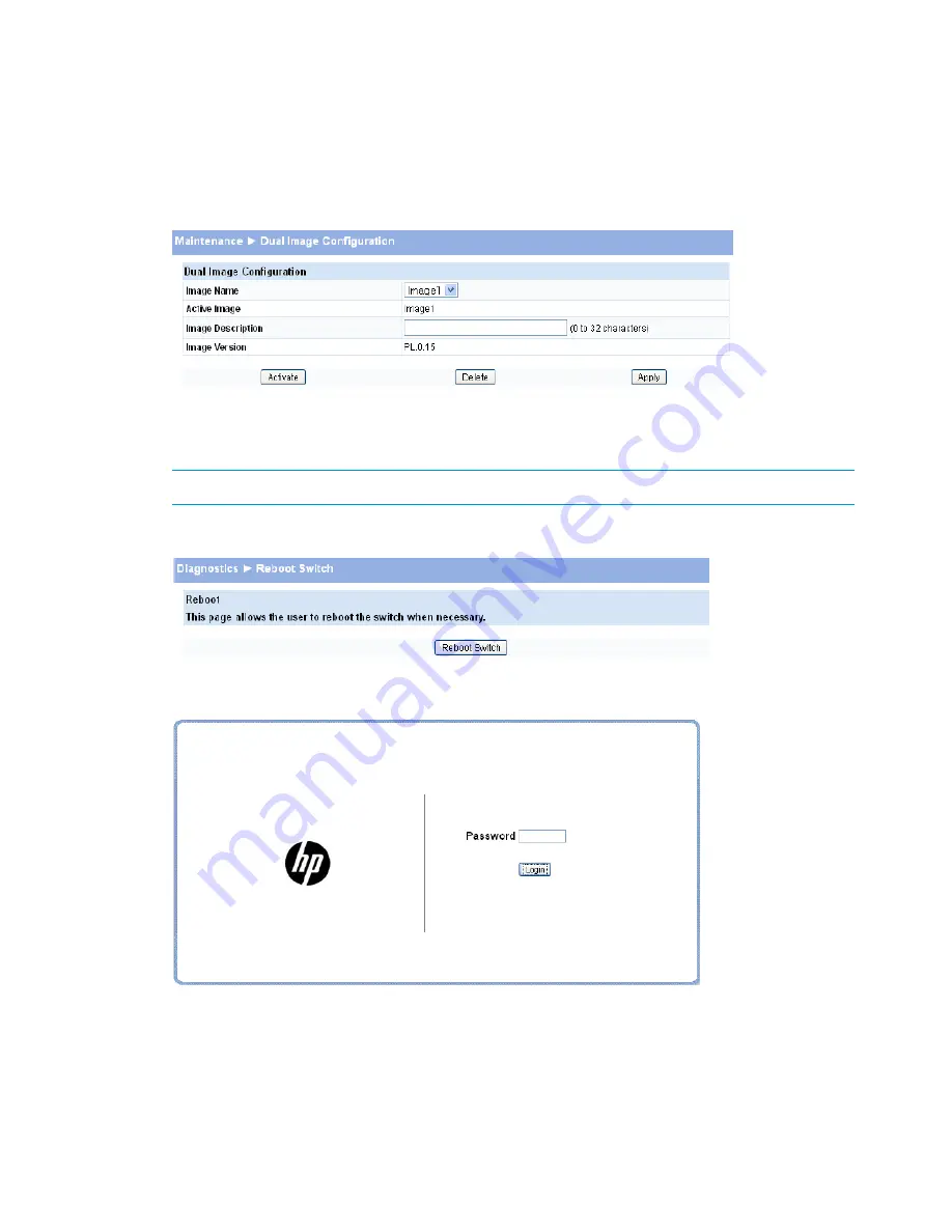
Note that, in this example, the image was downloaded as the inactive (backup) image. To
complete the update process and to activate the backup image as the operating software,
use the Dual Image Configuration page.

In the following example, Image1 is the active image, and Image2 is the newly updated
backup image. By clicking

Activate

Image2 will be activated on the next reboot (and Image1

will become the inactive backup image).

10.

(Optional) Add a description for the selected image (Image2) and click

Apply

.

11.

Click

Activate

to activate the selected image on the next reboot.

NOTE:

You can verify the next active image by viewing the

Status > Dual Image

screen.

12.

Click

Diagnostics > Reboot Switch

, and then click

Reboot Switch

to complete the update.

Wait for the switch to reboot and display the login page.

Password Manager

Use the Password Manager to change the password used to access the Web interface.

To display the Password Manager page, click the

Maintenance > Password Manager

.

64

Maintenance Pages

Summary of Contents for 1810-24

Page 1: ...listed on this page unless otherwise noted This guide does not provide information about upgrading or replacing switch hardware The information in this guide is subject to change without notice Applicable Products HP 1810 8 Switch J9800A HP 1810 8G Switch J9802A HP 1810 24 Switch J9801A HP 1810 24G Switch J9803A HP Part Number 5998 7093 Published January 2015 Edition 1 ...

Page 2: ...ucts and services are set forth in the express warranty statements accompanying such products and services Nothing herein should be construed as constituting an additional warranty HP shall not be liable for technical or editorial errors or omissions contained herein UNIX is a registered trademark of The Open Group Acknowledgments Microsoft Windows Windows XP and Windows NT are U S registered trad...

Page 3: ...ry page 14 LLDP Statistics page 15 Trunk Status page 16 MAC Table page 17 Loop Protection Status page 18 Spanning Tree Status page 19 Green Features Status page 21 Dual Image Status page 22 Clock Status page 23 3 Network Setup 25 Get Connected 25 Simple Network Time Protocol 27 Time Zone 28 Daylight Saving Time 28 4 Switching Pages 31 Port Configuration 31 Auto Detect and Configure Fiber Modules 3...

Page 4: ...ce 51 LLDP Remote Device 52 Energy Efficient Ethernet 52 9 Diagnostics 54 Ping Test 54 Log Configuration 54 Reboot Switch 55 Factory Defaults 56 Support File 56 Locator 57 10 Maintenance Pages 59 Backup Manager 59 Example Backing Up a Configuration File 60 Update Manager 61 Example Updating the Switch Software 62 Password Manager 64 Dual Image Configuration 65 1 1 Support and other resources 67 Co...

Page 5: ...et includes the following Quick Setup Guide a printed guide shipped with your switch Provides illustrations for basic installation and setup guidelines Regulatory and Safety Information printed documentation shipped with your switch Includes Regulatory statements and standards supported by the switch along with product specifications Installation and Getting Started Guide HP Web site only Provides...

Page 6: ...ession HTTPS timeout 5 HTTPS sessions 12 Trunk configuration 1810 24 1810 24G 4 Trunk configuration 1810 8 1810 8G 8 Trunk membership ports 1810 24 1810 24G 7 Trunk membership ports 1810 8 1810 8G 64 VLANs 4094 VLAN IDs 0 7 VLAN priority levels 1 Syslog servers 100 total storage 10K Buffered logs 1 Maintenance users 8 chars 64 chars Password length 2 Images 6 ...

Page 7: ...rating system and browser support page 7 for web browser requirements Thereafter use the Web interface to configure a different IP address or configure the switch as a DHCP client so that it receives a dynamically assigned IP address from the network NOTE If you enable DHCP for IP network configuration the switch must be connected to the same network as the DHCP server You will need to access your...

Page 8: ...wser and enter the IP address of the switch in the Web browser address field 2 On the Login page enter the password if one has been set and then click Login By default there is no password After the initial log on the administrator may configure a password NOTE To set passwords see Password Manager page 64 Figure 1 Login Page Interface layout and features Figure 2 shows the initial view 8 Getting ...

Page 9: ... For information on the Web Applet see Web Applet page 10 Common page elements Click on each page to display a help panel that explains the fields and configuration options on the page Click to send the updated configuration to the switch Configuration changes take effect immediately NOTE Configuration changes take effect immediately and are saved to the system configuration file after a 1 minute ...

Page 10: ...atus parameters of individual ports The Web Applet enables easy system configuration and Web based navigation Figure 3 Web Applet Port Configuration and Summary You can point to any port to display the following information about the port Auto Negotiation Status Speed Left click a port to display its Port Configuration page or right click and select from the menu to display its Port Configuration ...

Page 11: ...ingle color LEDs to indicate the Link Activity on the Left port LED and the Speed status indicated by the Right port LED The left port LED indicates link status as follows On The port is enabled and receiving a link indication or other signal from the connected device Blinking The port has network activity Off The port has no active network cable connected is not receiving link signal or is disabl...

Page 12: ...a Fast Ethernet switch The software and Boot ROM version are also displayed System Description Enter the preferred name to identify this switch A maximum of 31 alpha numeric characters including hyphens commas and spaces are allowed This field is blank by default System Name Enter the location of this switch A maximum of 31 alpha numeric characters including hyphens commas and spaces are allowed T...

Page 13: ...to increment beyond 100 and the oldest entries are deleted for example if 200 log entries were generated since the system was last restarted or the log file was cleared then the log file would display entries 101 200 To display the Log status page click Status Log in the navigation pane Figure 5 Log Status page Click the arrows next to the column headings to sort the list by the column in ascendin...

Page 14: ...lps to identify what has been configured on this port The displayed values are accumulated after the last clear operation Refreshing the page shows the latest statistics which provide per port statistics on packets transmitted and received for all the ports Scroll down the page to view the Port Statistics table which provides per port statistics on packets transmitted and received To display the P...

Page 15: ...ith Error The packet count for Broadcast packets received on the port Broadcast Received Packets The number of packets transmitted out of that port with out any packet errors Transmitted Packets w o Errors The number of packets transmitted out of the port with packet errors Transmitted Packets with Errors The number of packet collisions Collisions The number of Ethernet pause frames transmitted Th...

Page 16: ...eliness interval has expired Age Outs Time when an entry was created modified or deleted in the tables associated with the remote system Time Since Last Update LLDP Interface Statistics List of interfaces present or configured on the system Interface The number of LLDP frames transmitted on the corresponding port Transmitted Frames The number of valid LLDP frames received by this LLDP agent on the...

Page 17: ... disabled administratively When disabled no traffic will flow The messages that members of the trunk exchange in order Admin Status to manage the trunk LACPDUs will be dropped but the links that form the Trunk will not be released The default is Enable Displays whether the link is up or down Link Status Displays whether Static mode has been enabled on the trunk When static mode is enabled the trun...

Page 18: ... source port used for internal management on the switch Shows whether the MAC address is dynamically learned or whether this is a management address MAC Type Click the Refresh link above the page to re display the page with current data from the switch Loop Protection Status page The Loop Protection Status page displays a summary of loop protection configured data on the switch and on each port an...

Page 19: ...he number of loops detected on this interface since the last system boot or since statistics were cleared Loop Count The current loop protection status of the port Status Whether a loop is currently detected on the port Loop The time of the last loop event detected Time of Last Loop Click Clear to reset all counters to 0 Click the Refresh link above the page to re display the page with the latest ...

Page 20: ...Guarded Interfaces Interfaces with the BPDU Guard parameter currently set BPDU Protected Interfaces Interfaces with the BPDU Filter parameter currently set BPDU Filtered Interfaces The port number Interface The priority and port index used by the Spanning Tree protocol Interface ID The current Spanning Tree port role The port role can be one of the following values Role RootPort A forwarding port ...

Page 21: ...ently in use on the port Hello Time A yes no value Yes indicates a switched link with only two nodes No indicates a shared network segment with more than two nodes The value may be automatically computed or explicitly configured Point to Point A yes no value Yes means there are no bridges attached to this port No means there are or might be bridges attached The value may be automatically Edge comp...

Page 22: ...edium Low or Off Default value is Off Intensity Level The time of day when the configured LED Intensity Level is activated Start Time The number of hours the configured LED Intensity Level is in effect Duration The current setting Yes or No that indicates if the LED intensity levels will change daily at the configured time Recur Daily EEE Interface Status The port number Interface Indicates if the...

Page 23: ...rsion of the firmware image Version The configured descriptions for the images Description For instructions on configuring the active image see Dual Image Configuration page 65 Clock Status page The Clock Status page displays the current time time zone and Daylight Savings Time settings To display the Clock page click Status Clock in the navigation bar Figure 14 Clock Status page Table 1 1 Clock S...

Page 24: ...ngs Time Enabled Clock adjustment made for Daylight Savings time Disabled No clock adjustment will be made for Daylight Savings time Recurring The settings will be in effect for the upcoming period and subsequent years Non Recurring The settings will be in effect for only one period i e they will not carry forward to subsequent years For instructions on configuring the system time see Simple Netwo...

Page 25: ...k Setup Get Connected As shown in the example configuration in Figure 15 the switch has been configured to acquire its IP address through DHCP In this example access to the management software is restricted to members of VLAN 1 Figure 15 Get Connected Page Table 12 Get Connected Fields Description Field Network Details Select the type of network connection Protocol Type Static Select this option t...

Page 26: ...management port Any change in configured management VLAN ID may cause disruption in connectivity when the network protocol is configured to be DHCP this is because the switch acquires a new IP Address because the management subnet has changed To re connect to the switch the user must determine the new IP address assigned by the DHCP server Access to the management software also requires the select...

Page 27: ...e click Network Setup SNTP in the navigation pane Figure 16 SNTP Page Table 13 SNTP fields Description Field Select to enable SNTP client mode Clear to disable SNTP client mode When disabled the system time increments from 00 00 00 1 Jan 1970 which is set at bootup Enable SNTP Specify the IP address of the SNTP server to send requests to SNTP NTP Server Specify the server s UDP port to listen for ...

Page 28: ...oot session the changes take effect immediately Click the Refresh link above the page to re display the page with current settings from the switch To view a summary of clock and time zone information click Status Clock in the navigation pane Daylight Saving Time The Daylight Saving Time page is used to configure if and when Daylight Saving Time DST occurs for your time zone When configured the sys...

Page 29: ... to from DST occurs Month Set the month when the change to from DST occurs Hours Set the hour of the day when the change to from DST occurs Minutes Set the minutes in the hour when the change to from DST occurs When Non Recurring is selected as the DST mode the following fields display Month Set the month when the change to from DST occurs Date Set the day of the month when the change to from DST ...

Page 30: ...To view a summary of clock and DST information click Status Clock in the navigation pane 30 Network Setup ...

Page 31: ...the appropriate settings When a fiber module is inserted or changed the link speed menu shows the available speed options To display the Port Configuration page click Switching Port Configuration in the navigation pane Figure 19 Port Configuration Page NOTE The display and the content of this page changes based on the physical port selected For example if the selected port is an optional copper fi...

Page 32: ...k Apply to save any changes for the current boot session the changes take effect immediately Port Mirroring Port mirroring sends a copy of all packets sent and or received on one port the source port to another port the destination port for monitoring and analysis by an external network analyzer Multiple switch ports can be configured as source ports with each port mirrored to the same destination...

Page 33: ...ce ports but trunks can be selected as source ports NOTE The Source Port CPU can be mirrored to an external port to debug traffic to and from the CPU Click Apply to save any changes for the current boot session the changes take effect immediately Flow Control When a port becomes oversubscribed it may begin dropping all traffic for small bursts of time during the congestion condition This can lead ...

Page 34: ...ume less power than the normal high performance mode To display the Green Features configuration page click Switching Green Features in the navigation pane Figure 23 Green Features Table 20 Get Connected Fields Description Field Port Energy Saving Configuration Enable power save mode when there is no link This feature is disabled by default Auto Port Power Down EEE Energy Efficient Ethernet is des...

Page 35: ...ue is Yes Recur Daily Click Apply to save any changes for the current boot session the changes take effect immediately Loop Protection Loops in a network can consume switch resources and degrade performance Detecting loops manually can be very cumbersome and time consuming The HP 1810 series switch software provides an automatic Loop Protection feature Loop Protection may be enabled or disabled gl...

Page 36: ...use this feature Interface Loop Protection If Loop Protection is enabled on a port select one of the following actions to occur when a loop is detected Action Log The event is logged and the port remains operational Shutdown port The port is shut down for the configured period Log and Shutdown Port The event is logged and the port it shut down for the configured period If Loop Protection is enable...

Page 37: ...ation pane Figure 25 Spanning Tree Table 22 Spanning Tree Fields Description Field Spanning Tree Bridge Configuration Enable the Spanning Tree protocol mode globally This feature is disabled by default Protocol Mode Specify the protocol RSTP or STP RSTP is set by default Protocol Version Specify an STP RSTP bridge priority value between 0 61440 The default is 32768 Bridge Priority Interval between...

Page 38: ...rd is enabled on a port that port cannot be selected as the root port even if it receives superior STP BPDUs The port is assigned an alternate port role and enters a Root Guard blocking state if it receives superior STP BPDUs Select this option to enable root guard for the port It is not selected by default With TCN guard enabled a port does not propagate received topology change notifications and...

Page 39: ...he Advanced Security page click Security Advanced Security in the navigation pane Figure 26 Advanced Security Page Table 23 Advanced Security Fields Description Field Activate storm control protection for broadcast and multicast globally in the system The default threshold is 64K pps on the 1810 Gigabit switches and 4K pps on the Fast Ethernet switches Clear to not use the Storm Control feature St...

Page 40: ...erver must have a public key certificate The switch can generate its own certificates or you can generate these externally and download them to the switch Certificates generated by the switch are self signed that is the validity of the information provided in the certificate is attested to by the switch itself Downloaded certificates can also be self signed by a server other than the switch or the...

Page 41: ...nable or disable HTTPS Admin Mode or change the timeout settings click Apply to save the changes for the current boot session the changes take effect immediately NOTE Download or regenerate a certificate when the previous certificate has expired or when you have reason to suspect that security has been breached and the certificate has been taken for use by another server Downloading SSL Certificat...

Page 42: ...encrypting key exchanges and are used independent of the certificate The weak version uses a cipher strength of 512 bits and the strong version uses a cypher strength of 1024 bits Browser settings determine which DH file parameters are requested at the start of the SSL session 5 Click Download To view that status of the update you can view the Status Log page 6 To return to the Secure HTTP Configu...

Page 43: ... a partner system to be able to aggregate its member ports Members of a trunk must be either all static or all dynamic and all ports belonging to a trunk must have the same Full Duplex speed Trunk Configuration and Membership IMPORTANT Configure port trunking before you connect the trunked links between switches Otherwise a broadcast storm could occur If you need to connect the ports before config...

Page 44: ...ured as LACP Active or Passive RSTP can be enabled on a trunk When RSTP is either enabled or disabled on a trunk the individual Port members lose their STP configuration and will take on the trunk s configuration When ports are removed from a trunk the port members return to their earlier configured STP states An active port LACP and Static active members added to a trunk loses port VLAN membershi...

Page 45: ...Figure 31 Static Trunk Mode CAUTION Removing a port from a trunk can create a loop and cause a broadcast storm When you remove a port from a trunk where spanning tree is not in use HP recommends that you first disable the port or disconnect the link on that port LACP Trunk Modes There are two types of LACP Trunk Modes LACP Active and LACP Passive In LACP Active a trunk is initiated and maintained ...

Page 46: ...ive and Passive Trunking Capacities Trunking Capacity Feature HP 1810 8 Switch J9800A HP 1810 24 Switch J9801A HP 1810 8G Switch J9802A HP 1810 24G Switch J9803A 4 12 4 12 Trunks supported 7 8 7 8 Maximum ports in a trunk 46 Trunks ...

Page 47: ...on a VLAN An end station may omit the tag or the VLAN portion of the tag in which case the first switch port to receive the packet may either reject it or insert a tag using its default VLAN ID A given port may handle traffic for more than one VLAN but it can only support one default VLAN ID HP 1810 series switches support up to 64 VLANs VLAN Configuration Use the VLAN Configuration page to define...

Page 48: ...terface The VLAN ID that this port will assign to untagged frames or priority tagged frames received on this port range 1 4094 default 1 The PVID is not user configurable PVID and always corresponds to VLAN ID of the port s untagged VLAN membership You assign ports to VLANs on the VLAN Participation Tagging page The PVID value displays as None if all the VLANs are configured as tagged on this port...

Page 49: ...t or trunk to participate in a VLAN its tagging policy must be defined By default all ports and trunks are configured as untagged members of VLAN1 and are excluded from all other newly created VLANs Tag Untag Exclude All You can configure each port individually or use the Tag Untag Exclude All box to configure all ports at once Click the box until the appropriate option is displayed E exclude from...

Page 50: ...s The application is responsible for starting each transmit and receive state machine appropriately based on the configured status and operational state of the port LLDP Configuration Use the LLDP Configuration page to specify global LLDP parameters and to configure the protocol on individual ports To display the LLDP Configuration page click LLDP LLDP Configuration in the navigation pane Figure 3...

Page 51: ...mation with the LLDP PDUs The default is enabled Transmit Mgmt Info Click Apply to save any changes for the current boot session the changes take effect immediately LLDP Local Device Use the LLDP Local Device page to view information about devices on the network for which the switch has received LLDP information To display the Local Device page click LLDP Local Device in the navigation pane Figure...

Page 52: ...iated with the remote system Chassis ID The physical address of the port on the remote device that sent the LLDP data Port ID The port description configured on the remote device If the port description is not configured the field is blank Port Description The system description configured on the remote device If the system description is not configured the field is blank System Name The capabilit...

Page 53: ...ding data Tx Tw The time in microseconds that the receiving link partner requests the transmitting link partner to wait after leaving the low power idle mode before sending data Rx Tw An alternate value for the time that the receiving link partner requests the transmitting link partner to wait after leaving LPI mode before sending data Fallback Receive Tw Echo sent to the link partner of the lates...

Page 54: ...efault 3 seconds Interval Specify the size of the ping packet to be sent Range 0 5120 Default 0 Size Click Apply to ping the specified host The output includes the following data IP Address The IP address of the device that was pinged Sequence The Internet Control Message Protocol ICMP number of the packet starting from 0 Time The ping reply status Transmitted Packets The number of packets sent Re...

Page 55: ...he user of a system error Info Provides the user with system information Debug An internal note to reconcile programming code Specify a logging level A log records messages equal to or above a configured console logging level Info by default Buffered Logging Level Enable the switch to send Syslog messages Disabled by default Enable Syslog Specify the IP address of a host on the network running a S...

Page 56: ...k Diagnostics Factory Defaults CAUTION Backup the current configuration file prior to restoring the factory defaults configuration See Backup Manager page 59 for instructions Figure 43 Factory Defaults Page Click Reset Configuration to restore the system to the default settings Support File Use the support file page to display summary information for the switch on a single page To display the Supp...

Page 57: ... summaries Port mirroring configuration Loop protection status per interface Spanning tree bridge and interface status and configuration and port settings To save the Support File data to a file click Save As located at the top and bottom of the page You can print the text from your text editor Alternatively your browser may support printing only the frame that contains the data that is it exclude...

Page 58: ...Select Locate and click Apply to cause the Locator LED on the switch to blink for 30 minutes 58 Diagnostics ...

Page 59: ...server operating on the system network If a TFTP backup is to be performed enter the IP address of the TFTP server Server IP TFTP backup only If a TFTP backup is to be performed enter the file name with which backup must be saved This can differ from the actual file name on the switch File Name TFTP backup only Select the image or file to be backed up Backup Type Code The entire image is backed up...

Page 60: ...ser other than Microsoft Internet Explorer such as Firefox or Mozilla the download of the attachment should work as expected Example Backing Up a Configuration File Follow these instructions to back up a configuration file 1 In the Backup Method field select the protocol to use to upload the file to the system To save the file on a local or network drive select HTTP To save the file on a TFTP serv...

Page 61: ...p image on the switch is being updated from a TFTP server For example if the image1 file is being used as the currently active image running on the switch then the image2 file is the backup file to be updated To display the Update Manager page click Maintenance Update Manager in the navigation pane Figure 47 Update Manager Page Table 36 Update Manager Fields Description Field Select the protocol t...

Page 62: ...ncoded If Code is selected as the update type select which of the two images stored on the switch is to be updated Image for Code updates only Active The uploaded image will replace the currently active image Backup The uploaded image will replace the backup image Example Updating the Switch Software CAUTION It is recommended that you back up the image file before updating it See Backup Manager pa...

Page 63: ...message displays on the Update Manager page Code Configuration download through HTTP TFTP is in Progress Please wait When the transfer is complete a window like the following displays 8 Click OK Update Manager displays the following status message Update Manager 63 ...

Page 64: ...oot and Image1 will become the inactive backup image 10 Optional Add a description for the selected image Image2 and click Apply 1 1 Click Activate to activate the selected image on the next reboot NOTE You can verify the next active image by viewing the Status Dual Image screen 12 Click Diagnostics Reboot Switch and then click Reboot Switch to complete the update Wait for the switch to reboot and...

Page 65: ...Image1 either fails or does not boot then the other image can be activated To display the Dual Image Configuration page click Maintenance Dual Image Configuration Figure 49 Dual Image Configuration Page Table 37 Dual Image Configuration Fields Description Field Select the image you want to perform an action on You can activate the selected image delete it or configure a description of it Options a...

Page 66: ...To view dual image status information click Status Dual Image Status in the navigation pane 66 Maintenance Pages ...

Page 67: ...he latest product enhancements newest driver versions and firmware documentation updates as well as instant access to numerous other product resources After subscribing locate your products by selecting Business support and then Storage under Product Category Typographic conventions Table 38 Document conventions Element Convention Blue text Table 38 page 67 Cross reference links and e mail address...

Page 68: ...iables Emphasized monospace text Monospace bold text WARNING Indicates that failure to follow directions could result in bodily harm or death CAUTION Indicates that failure to follow directions could result in damage to equipment or data IMPORTANT Provides clarifying information or specific instructions NOTE Provides additional information TIP Provides helpful hints and shortcuts 68 Support and ot...

Page 69: ...cumentation that meets your needs To help us improve the documentation send any errors suggestions or comments to Documentation Feedback docsfeedback hp com Include the document title and part number version number or the URL when submitting your feedback 69 ...

Page 70: ...mes 32 L Link Layer Discovery Protocol 50 see also LLDP LLDP 50 see also Link Layer Discovery Protocol configuration 50 local device 51 remote device 52 LLDP Statistics page 15 Locator LED 57 log configuration 54 Log Status page 13 loop protection 35 Loop Protection Status page 18 M MAC Table page 17 maintenance pages 59 N network connection 7 O operating system 7 P Password Manager 64 Ping Test 5...

Page 71: ...3 dynamic 43 modes 44 disabling 44 LACP 45 static 45 static 43 typographic conventions 67 U updating switch software 62 V Virtual LAN 47 see also VLAN VLAN 47 see also Virtual LAN configuration 47 ports 48 tagging 49 W Web Applet 10 web interface logging on 8 web sites HP Subscriber s choice 67 71 ...

Reviews: