


32
The appearance and installation methods of slide rails depend on the slide rail types.
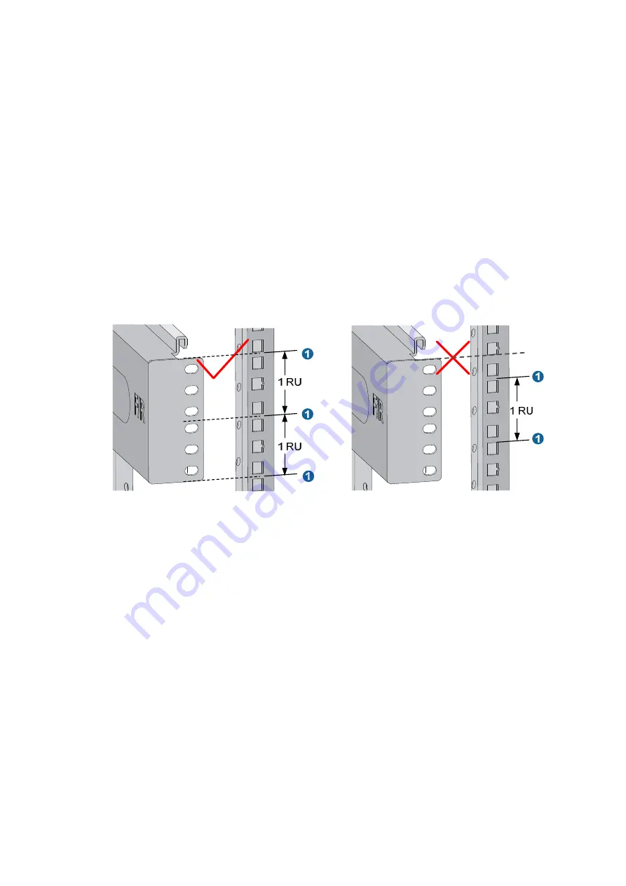
This section uses a 19-inch rack as an example to describe the installation procedures. The rack unit (RU)
(44.45 mm, or 1.75 in) measures the height of rack posts. As shown in
, each 1 RU has three
mounting holes with center-to-center separations of 15.88 mm (0.63 in), 15.88 mm (0.63 in), and 12.70
mm (0.5 in). When installing the slide rails, make sure the bottom edge of the slide rails aligns with the
middle of the narrowest separation between mounting holes.
To install the slide rails:
1.
Mark the position of the slide rail on the right rack posts.
Make sure the clearance above the slide rail is sufficient for the switch. For the dimensions of the
12500 switch, see "Appendix A Technical specifications."
2.
Align the screw holes on the two sides of the slide rail with the corresponding mounting holes on
the right rack posts, and then fasten the screws.
3.
Repeat steps 1 and 2 to install the other slide rail to the left rack posts.
Keep the two slide rails at the same height so that the switch can be placed evenly.
Figure 29
Locating the installation position of the slide rail
Installing cage nuts
Before mounting the chassis to the rack, install cage nuts to the front square-holed brackets of the rack.
To install cage nuts to the rack:
1.
Face the front of the rack.
2.
Align the mounting bracket with the left rack post, making sure its bottom edge and the slide rail
are level. Mark the positions of the cage nuts on the rack post according to the mounting holes on
the mounting bracket. (Each mounting hole on the mounting bracket corresponds to one cage nut.)
3.
Insert one edge of a cage nut into the hole.
4.
Compress the other edge of the cage nut to push the cage nut fully into the hole.
5.
Repeat steps 2, 3, and 4 to install cage nuts to all the marked positions on the right rack post.
Summary of Contents for 12500 Series
Page 36: ...30 Figure 28 Installing an upper expansion cable management bracket 1 2 3 4 5 6 7 ...
Page 98: ...92 Figure 70 Replacing a card for the 12504 A Card to be removed B Card to be installed ...
Page 128: ...122 Figure 81 Loopback operation on an optical transceiver ...
Page 143: ...137 Figure 96 Example of a device label ...
Page 146: ...140 Cable management examples Figure 100 Network cable management ...