b.
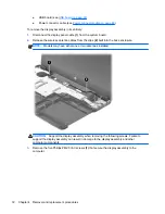
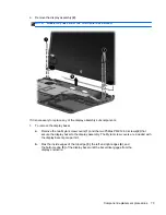
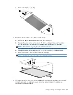
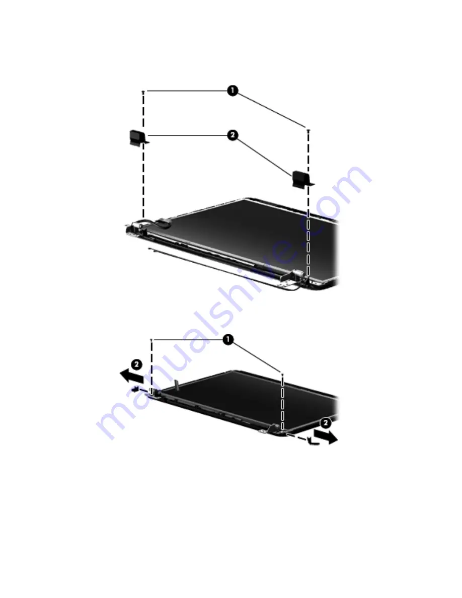
Remove the two Phillips PM2.5×4.0 screws
(1)
that secure the top hinge covers to the
display enclosure, and then remove the top hinge covers
(2)
.
c.
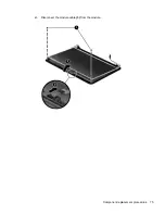
Remove the two Phillips PM2.0×3.0 screws
(1)
that secure the side hinge covers to the
display enclosure, and then remove the side hinge covers
(2)
.
4.
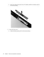
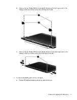
To remove the display panel, cable, and hinges:
a.
Position the display assembly with the top edge toward you.
Component replacement procedures
77
Summary of Contents for 2000
Page 1: ...HP 2000 Notebook PC Compaq Presario CQ58 Notebook PC Maintenance and Service Guide ...
Page 4: ...iv Safety warning notice ...
Page 22: ...3 Illustrated parts catalog Computer major components Computer major components 15 ...
Page 43: ...4 Remove the display bezel 3 36 Chapter 4 Removal and replacement procedures ...
Page 45: ...b Disconnect the module cable from the module 38 Chapter 4 Removal and replacement procedures ...
Page 82: ...d Disconnect the module cable 3 from the module Component replacement procedures 75 ...

