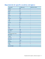
Country/region
Accredited agency
Applicable note number
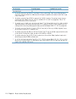
The United States
UL
2
1.
The flexible cord must be Type HO5VV-F, 3-conductor, 0.75mm
2
conductor size. Power cord set fittings (appliance
coupler and wall plug) must bear the certification mark of the agency responsible for evaluation in the country or region
where it will be used.
2.
The flexible cord must be Type SVT/SJT or equivalent, No. 18 AWG, 3-conductor. The wall plug must be a two-pole
grounding type with a NEMA 5-15P (15 A, 125 V ac) or NEMA 6-15P (15 A, 250 V ac) configuration. CSA or C-UL
mark. UL file number must be on each element.
3.
The appliance coupler, flexible cord, and wall plug must bear a “T” mark and registration number in accordance with the
Japanese Dentori Law. The flexible cord must be Type VCTF, 3-conductor, 0.75mm
2
or 1.25mm
2
conductor size. The
wall plug must be a two-pole grounding type with a Japanese Industrial Standard C8303 (7 A, 125 V ac) configuration.
4.
The flexible cord must be Type RVV, 3-conductor, 0.75mm
2
conductor size. Power cord set fittings (appliance coupler
and wall plug) must bear the CCC certification mark.
5.
The flexible cord must be Type H05VV-F 3X0.75mm
2
conductor size. KTL logo and individual approval number must be
on each element. Corset approval number and logo must be printed on a flag label.
6.
The flexible cord must be Type HVCTF 3X1.25mm
2
conductor size. Power cord set fittings (appliance coupler, cable,
and wall plug) must bear the BSMI certification mark.
7.
For 127 V ac, the flexible cord must be Type SVT or SJT 3 x 18 AWG, with plug NEMA 5-15P (15 A, 125 V ac), with UL
and CSA or C-UL marks. For 240 V ac, the flexible cord must be Type H05VV-F 3X0.75/1.00mm
2
conductor size, with
plug BS 1363/A with BSI or ASTA marks.
112 Chapter 8 Power cord set requirements
Summary of Contents for 2000
Page 1: ...HP 2000 Notebook PC Compaq Presario CQ58 Notebook PC Maintenance and Service Guide ...
Page 4: ...iv Safety warning notice ...
Page 22: ...3 Illustrated parts catalog Computer major components Computer major components 15 ...
Page 43: ...4 Remove the display bezel 3 36 Chapter 4 Removal and replacement procedures ...
Page 45: ...b Disconnect the module cable from the module 38 Chapter 4 Removal and replacement procedures ...
Page 82: ...d Disconnect the module cable 3 from the module Component replacement procedures 75 ...

