background image

26

Hoval STU Wood Pellet Boiler

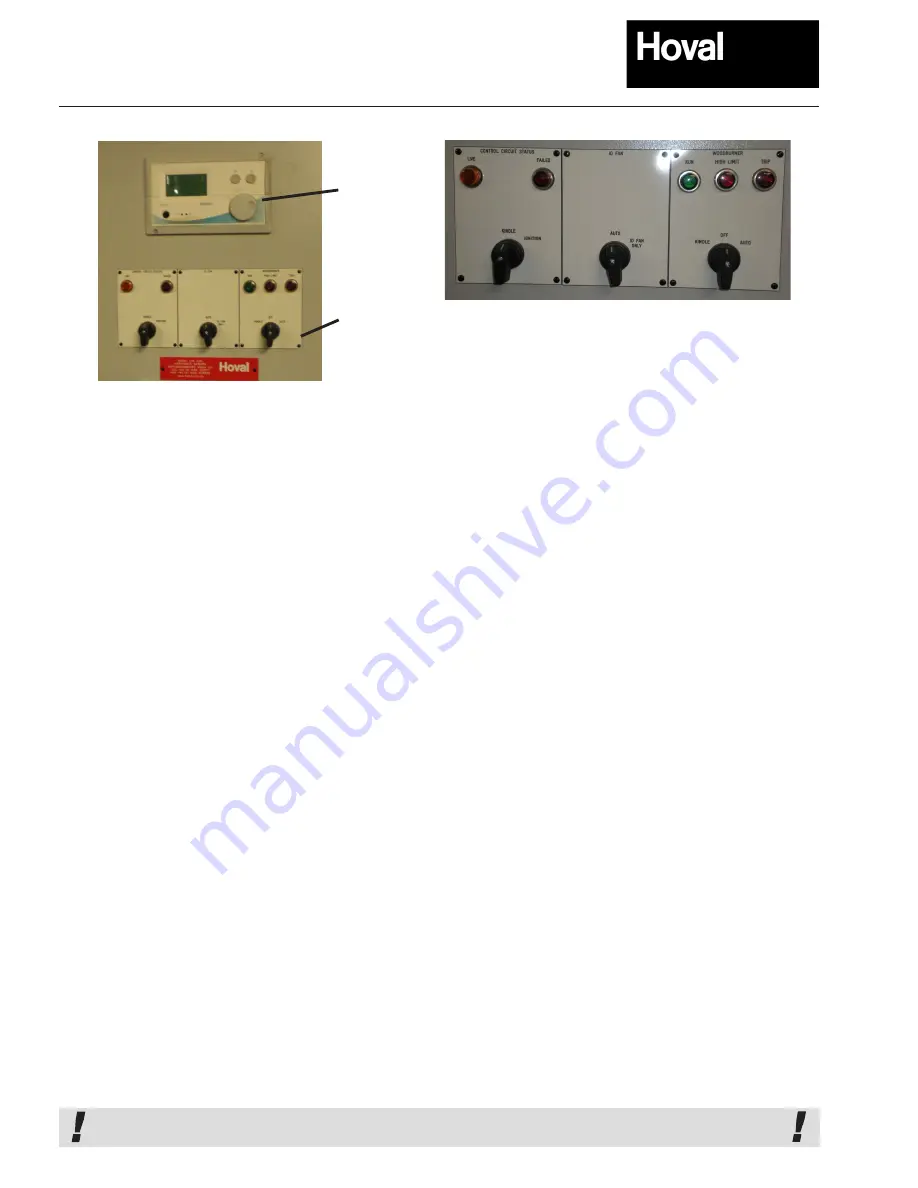
In addition to the stoker control panel (see below) a boiler flow temperature gauge is fitted at the front of the boiler.

Control Details and Safety Features

•  The stoker control panel consists of:


• 

Mains Isolator (not shown above)

• 

LRP control unit and Display.

• 

On/Off Switch with settings Kindle/Off/Auto.

• 

ID Fan Switch with settings Auto/ID Fan Only 

• 

Optional Ignition switch with settings Kindle / Ignition 

•  The LRP controller and display

 has a wide variety of settings 

available for fine control of the wood pellet-burning stoker. In normal 
operation  only  a  few  of  these  may  be  required  to  be  displayed 
but they can be altered at the time of commissioning to suit the 
site conditions. The following are the most common parameters 
available for display.

• 

Boiler Flow set point.

• 

Wood pellet feed speed.

• 

Oxygen set point.

•  The Mains Isolator will:

• 

Electrically isolate the stoker and pick-up auger(s). The  


isolator is provided with a lock-off facility.

•  The stoker Kindle/Off/Auto switch will:

• 

Turn the stoker off when in the off position.

• 

In the Auto position the stoker will be under control of  


the LRP and time clock or the Building Management   


System and will modulate to follow the load accordingly  


and may kindle if the set point water temperature is    


satisfied (includes frost protection).

• 

Kindle only, when in Kindle position (

Note 

the boiler will  


be held in a standby or kindle condition and there will  


be no frost protection in this position).

•  The Auto/ID Fan Only switch will:

• 

Normally be in the Auto position.

• 

I.D. Fan only position when the boiler door is opened.

•  The Kindle/Ignition switch (where fitted) will:

• 

Normally be in the kindle position.

• 

In the Ignition position the retort will be primed (from   


empty) with pellets and the ignition process started.   


The operator must ensure that the retort is totally 


emptied of pellets before starting the ignition process.

The Stoker Control Panel also houses a series of indicator lights 
as follows:

• 

Panel Live (Orange).

• 

Fuse Failed (Red).

• 

Stoker Run (Green).

• 

High Limit (Red).

• 

Trip (Red).

Under normal operation the LRP controller monitors and regulates 
the boiler water temperature. In addition to this, mounted in a pocket 
on top of the boiler are two thermostats. The first of these has a 
temperature dial, which can be adjusted in the range of 70-83

o

C, this 

effectively acts as a first limit stat, and if the boiler water temperature 
exceeds the set temperature the stoker will shut off and will only re-
fire once the water temperature has fallen. It should be set higher 
than the programmed water temperature setting in the LRP controller. 
The second stat is set at commissioning, usually 11

o

C above the first, 

and is a second or high limit stat. If the boiler temperature exceeds 
this limit then the stoker will shut off and the High Limit indicator will 
be illuminated. The stoker will not re-fire until this second limit stat 
is manually reset. 

Under normal operation the Stoker Run (green) light should show 
on the control panel. 

A fuse Fail or a motor Trip would illuminate the appropriate light - if 
illuminated the cause should be investigated prior to resetting.

The stoker control panel can be fitted or mounted on either side 

of the boiler or where requested can be supplied separately for 

mounting on a wall within the plant room. Site wiring will be re-

quired to connect the pellet auger feed motors, FD and ID fan 

motors, each must be connected via individual isolating switches 

that should be clearly labelled. In addition the flow temperature 

sensor, damper control on both FD and ID fans, burn back stat, 

combustion chamber pressure switch and lambda control will also 

require wiring back to the panel. This wiring is NOT generally part 

of the stoker installation unless arranged at the time of order.

IMPORTANT   - A  3 Phase 32A  400V supply is required for stoker and control panel operation.

LRP Controller

and Display

Screen

Selector 

Switches

Summary of Contents for STU Series

Page 1: ...Installation Operation and Maintenance Instructions STU wood pellet fired hot water boiler 150 1000kW STUman May 2010 WS2...

Page 2: ...n Guidelines Entry to fuel Store 17 18 Typical Plantroom Layouts 19 21 Boiler Door Handing 22 Boilerhouse Ventilation Open Vented Pressurised Systems 23 Flues and Chimneys 24 Filling The System With W...

Page 3: ...technical servicing or parts enquiries telephone fax or e mail Hoval quoting the boiler s serial number as above Tel 01636 593413 or 593435 Fax 01636 673532 e mail service hoval co uk or spares hoval...

Page 4: ...n and use of this appliance Fuel Quality Requirement The design of the boiler stoker pellet handling system and store is dependant on using the correct quality wood pellet fuel The pellets should be f...

Page 5: ...uel bed An optional ignition start system is available on request but this must be specified at the time of order The boiler comprises of a welded steel shell with a water jacket surrounding an oval c...

Page 6: ...of flue gases ensures close combustion control as the air supply is adjusted to match the fuel feed The standard stoker design incorporates an airless kindle feature This allows the boiler under norm...

Page 7: ...28 5 87 6 11 Water Flow Rate 82 71 C kg s 3 4 4 3 5 4 6 5 8 2 9 2 10 9 13 0 17 4 21 7 Hydraulic Resistance at 80 60 C kPa 0 2 0 3 0 4 0 6 0 6 0 8 1 1 1 6 1 8 1 9 Water Flow Rate 80 60 C kg s 1 9 2 4...

Page 8: ...40 235 235 235 235 235 235 275 Connections 1 Flow PN6 DN50 DN80 DN80 DN80 DN80 DN80 DN80 DN100 2 Return PN6 2xDN50 2xDN80 2xDN80 2xDN80 2xDN80 2xDN80 2xDN80 2xDN100 3 Safety valve BSP G1 1 2 G2 G2 G2...

Page 9: ...peration Connections 800 1000 1 Flow PN6 DN125 DN150 2 Return PN6 2xDN125 2xDN150 3 Safety valve BSP G2 G2 4 Drain BSP 2xG1 1 2 2xG1 1 2 5 Stat pockets BSP 2xG1 2 2xG1 2 6 Pressure switch BSP R3 4 R3...

Page 10: ...he boiler to suit specific plant room layout See Page 11 for a typical plant room layout Cyclone 800 1000 A mm 1389 1439 B mm 744 768 C mm 2368 1540 D mm 2227 2422 E mm 2615 2872 F mm 900 950 G mm 274...

Page 11: ...mensions and Technical Information Typical Layout Hoval STU Boiler with modular twin cyclone floor mounted ID fan and connecting ductwork Hatched ducting NOT by Hoval To suit specific plant room layou...

Page 12: ...iltration in use The elements are easily replaced by vertically removing the existing elements from the unit and replacing with a new element Accordingly it is essential to locate the filter with a mi...

Page 13: ...ught Fan Incoming Electrical Supply Type Motor kW Absorbed power kW STU 150 CF 150 Halifax 1 5 0 89 3N 50Hz 400 230V 10A max STU 200 CF 200 Halifax 1 5 0 86 3N 50Hz 400 230V 10A max STU 250 CF 250 Hal...

Page 14: ...CF Biomass Filter Typical units 14 Measurements in mm CF 500 unit Clearance of 1000mm required above the unit for filter withdrawal replacement...

Page 15: ...spection lids Cladding and Lagging 75mm thk Control panel RCA 25 DD pulse valve Compressed air reservoir Particulate discharge tray Clearance of 1000mm required above the unit for filter withdrawal re...

Page 16: ...outlet Outlet Outlet Fluing to chimney Typical Layout STU 200 Wood Pellet Boiler with CF 200 Biomass Filter Hatched ducting not by Hoval Note easy radius bends should be used 16 Side Elevation View o...

Page 17: ...ke build bunker store These typically require a larger floor area and are less effective in terms of the available recoverable volume of fuel Some profiling of the bunker base should be considered min...

Page 18: ...l consumption would be estimated based on the loading placed on the boiler Wood Pellet fuel store to be sized to accommodate a minimum of 10 15 days anticipated fuel use 3 Delivery Size The fuel suppl...

Page 19: ...s of dead volume b Slots active pick up locations c Gate valve required to isolate individual silos 2 STU wood pellet boiler 3a Flexible auger Note requirements for long radius bends 1 5 2m Note maxim...

Page 20: ...20 Hoval STU Wood Pellet Boiler Typical Plantroom layouts GENERAL ARRANGEMENT OF A STOKER AND A FABRIC SILO GENERAL ARRANGEMENT OF STU BOILER WITH TWIN EB BOOT TABLES AND PROFILING...

Page 21: ...21 Hoval STU Wood Pellet Boiler Typical Plantroom layouts GENERAL ARRANGEMENT OF STU BOILER AND A FABRIC TROUGH BUNKER INDICATIVE LAYOUT OF STU BOILER WITH GRP SILO...

Page 22: ...lock nuts on the new hinge side are fully tightened 5 Loosen locknuts on the new opening side so that a seal is obtained all round the fibre joint Important Always have two nuts tightened to prevent t...

Page 23: ...idelines The supply of air to a space housing the boiler by mechanical means should be mechanical inlet with natural or mechanical extraction Mechanical extract ventilation with natural inlet must not...

Page 24: ...is particularly important on any horizontal section The flue should include some pressure relief and or draught stabiliser as Appropriate Flues should be supported independently to prevent any undue...

Page 25: ...ains is treated Even the water in closed systems will promote corrosion unless treated For these reasons Hoval strongly recommend that when necessary the system be thoroughly cleaned prior to the use...

Page 26: ...e starting the ignition process The Stoker Control Panel also houses a series of indicator lights as follows Panel Live Orange Fuse Failed Red Stoker Run Green High Limit Red Trip Red Under normal ope...

Page 27: ...en stoker running but the error message will still be retained on the display until cleared by the operator This is accessed via the manual status menu as detailed on page 28 However it is important t...

Page 28: ...eters and manually set plant status only Level 2 As Level 1 and change times schedules set points view menus Level 3 As Level 2 with change all settings and view all parameters Level 4 As Level 3 with...

Page 29: ...using the controller The parameters shown here will be directly related to your plant applications and requested access levels to suit your experience These parameters may be changed by you e g if a s...

Page 30: ...ndicated whether the Boiler Fan is called to run I On O Off Delayed FD Fan All Levels Indicates whether the Stoker Fan is called to run I On O Off Trickle Feed Rate Level 4 This sets the pellet feed t...

Page 31: ...All other manufacturers equipment has been installed and commissioned e g pressurisation units A suitable safety valve has been fitted to the boiler together with associated discharge pipework Suffici...

Page 32: ...ting The boiler will be left with water in the water dump device full to within 50mm of the top of the container The LRP boiler control thermostat is adjusted to suit the system design flow and temper...

Page 33: ...t excessive manual input The stoker will automatically adjust the firing range to match the load with damper control on both the forced and induced draught fans Continuous O2 monitoring of the flue ga...

Page 34: ...ition of the fire within the retort to ensure that combustion is fully established using the sight glass on the front of the door of the boiler IMPORTANT Once the fire has established the isolating sw...

Page 35: ...D FAN only switch should be put to the ID fan only position to pull any residual fumes out of the boiler On the 600 1000kW boilers the boiler needs to be left to stand for 30 minutes The boiler door c...

Page 36: ...correctly NOTE No continuous make up of water should be taking place In this event check where a leak may be occurring or if pumping over is taking place Maintenance Boiler and Stoker Servicing In ad...

Page 37: ...so that the shear pin slot is at the top using the shear pin bar provided align the slot on the worm section remove broken pin and fit replacement If there is a jam or pin failure on the Pick Up Auge...

Page 38: ...38 Hoval STU Wood Pellet Boiler GRP SILO SPECIFICATION SHEET 2 85m Appendix A...

Page 39: ...39 Hoval STU Wood Pellet Boiler Appendix B Note The thermostatically operated valve has a red test button which will prove the valve opens when pressed held in...

Page 40: ...this sleeve to ensure correct operation of the wa ter dump device Removable cap Water dump container Boiler drain connection two per boiler Water dump thermal valve preset to open at 95 C Thermal valv...

Page 41: ...thermostat access cover Isolate the boiler control panel via the main isolator switch on the panel facia before removing this cover Remove cap and check the water level weekly Water should be within 5...

Page 42: ...amiliarisation Information Pellet Drop box Proximity level switch in pellet delivery auger transfer box Access cover to delivery auger to drive coupling shear pin Stoker delivery auger to drive coupli...

Page 43: ...nduced Draught Fan Actuator for Induced draught fan damper Smoke box condensate drain piperwork with trap Mains cold water supply Thermal valve preset to open at 95 C Cooling coil heat exchanger s con...

Page 44: ...Combustion chamber pressure sensing point with interconnecting pipework to pressure switch Clean this out weekly Appendix C Boiler Familiarisation Information Forced draught fan with motorised damper...

Page 45: ...oiler Familiarisation Information View of Combustion Chamber with pellets in the retort at the correct level for lighting Refractory fibre boiler door lining Cut out for sight glass opening Combustion...

Page 46: ...hanger Appendix C Boiler Familiarisation Information Remove insulated red cover below boiler door and lift off metal in spection panel to gain access to the optional 3kW electric ignition unit located...

Page 47: ...47 Hoval STU Wood Pellet Boiler Appendix C Boiler Familiarisation Information Optional 3kW electric ignition unit Lift off metal inspection panel...

Page 48: ...tch the Wood burner to the Off position found on the KINDLE OFF AUTO selector switch mounted on the control panel 3 Turn the separate I D Fan selector switch to I D Fan Only 4 Take care when opening t...

Page 49: ...sealed when refitted 8 Refit the spiral retarders 9 Clean the small hole for the combustion chamber pressure switch sensing point which is found on the L H S of the combustion chamber close to boiler...

Page 50: ...k on 8 If the fire is not established allow more time before turning the Pick up and Conveyor augers back on NOTE For a boiler fitted with an ignition system the above procedure should only be employe...

Page 51: ...rruption Burn back Fire has tracked back along the Thermostat initiation conveyor tube Possible causes are Conveyor motor tripped see below or shear pin failure burn back thermostat malfunction or a p...

Page 52: ...52 Hoval STU Wood Pellet Boiler Notes...

Page 53: ...53 Hoval STU Wood Pellet Boiler Notes...

Page 54: ...thgate Newark Notts NG24 1JN Tel No s 01636 59413 or 593435 Service Desk direct dial numbers 01636 593412 Spares Desk direct dial Fax 01636 673532 e mail service hoval co uk spares hoval co uk STUman...

Reviews: