background image

9

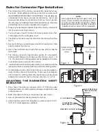
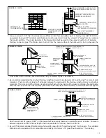
1.  The crimped end of the chimney connector fits inside the furnace 

flue collar.  Install additional chimney connectors and elbow with 
the CRIMPED END TOWARD THE FURNACE.  This will allow any 
condensation in the flue to run back into the furnace.  Use 6" dia. 
steel pipe and elbows for connection to chimney.  Never use less 
than 24 gauge and although blued steel is satisfactory, high temp 
painted black is much more desirable. (See Figure 8)

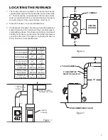
2.  Slope any horizontal pipe upward toward the chimney at least 1/4 

inch for each foot of horizontal run.

3.  You must have at least 18 inches of clearance between any hori

-

zontal piping and the ceiling.(See Fig. 5)

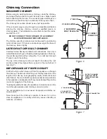
4.  The chimney connector must not extend into the chimney flue. (See 

Fig. 9)

5.  Seal each chimney connector pipe joint with furnace cement.  Also 

seal the pipe at the chimney.

6.  Use 3 sheet metal screws at each chimney pipe joint to make the 

piping rigid.

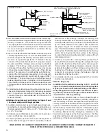
7.  The chimney connector may include a section for a barometric 

draft regulator between the furnace and the chimney (Fig. 6, 7, & 
10).  The barometric draft regulator must be installed in the same 
room (same pressure zone) as the furnace.

8.   Install the barometric draft regulator strictly in accordance with the 

instructions that are provided with the barometric draft regulator.

9.  A solid damper must be used in the chimney connecting pipes be

-

tween the flue collar and the chimney.  When used in conjunction 
with a barometric draft regulator, the solid damper must be placed 
between the barometric and the chimney. (See Fig. 6, 7, & 10)

ADJUSTING THE BAROMETRIC DRAFT 

REGULATOR

1.  Drill a hole in the chimney connector within 18" of the flue collar 

below the barometric draft regulator just large enough for the tube 
of the manometer.

2.  Build a fire after all chimney connections have been made.
3.  Use a manometer to measure the draft in the flue.
4.  Adjust the Barometric Draft Regulator to obtain a draft of 0.05 - 

0.06" W.C. under stable fire conditions.

RIGHT

WRONG

WRONG

6" SOLID DAMPER

6" BAROMETRIC

DRAFT REGULATOR

NON COMBUSTIBLE

INSTALLATION PER

NFPA 211

MEASURE FLUE DRAFT HERE

Figure 9

Figure 10

Rules for Connector Pipe Installation

NOTE:

A flue pipe shall not pass through an attic, roof 

space, closet or similar concealed space, a floor 

or ceiling of combustible construction. Where 

passage through a wall or partition is desired, 

installation must conform with UL standards.

Figure 8

Summary of Contents for 1357M

Page 1: ... FORCED AIR GAS OR OIL FIRED FURNACE U S ONLY FOR INSTALLATION AS A CENTRAL FURNACE ALL MODELS CERTIFIED UNDER UL 391 85591V 0602G CAUTION READALLINSTRUCTIONSCARE FULLY BEFORE STARTING THE INSTALLATIONOROPERATING THE FURNACE IMPROPER INSTALLATION MAY VOID YOUR WARRANTY DO NOT USE THIS FURNACE IN A MOBILE HOME OR TRAILER U S Environmental Protection Agency Certified to comply with 2015 particulate ...

Page 2: ...er or 5 16 Socket W Ratchet Safety Glasses MATERIAL 6 Pipe 6 Elbow Collar and Thimble as required 24 gauge min 1 2 Sheet Metal Screws 6 Inside diameter Listed Residential Type or Building Heating Appliance Chimney or existing masonry chimney Electrical Wiring 6 Draft Regulator 1 2 Conduit Conduit Connectors Furnace Cement Manufacturer Recommends Rutland Black Code 78 or Equivalent Plenum and Duct ...

Page 3: ...AFETY NOTICE If this heater is not properly installed a house fire may result For your safety follow the installation directions Contact local building or fire of ficials about restrictions and installation inspection requirements in your area If not already installed we recommend that smoke detectors be installed CAUTION CLEANOUT OF THE HEAT EXCHANGER FLUE PIPE CHIMNEY AND DRAFTINDUCER IFUSED ISE...

Page 4: ...A 211 The address of the NFPA is Batterymarch Park Quincy MA 02269 11 Keep the ashpit section free of excess ashes Do not al low ashes to stack higher than the sides of the ash pan 12 DISPOSAL OFASHES Place ashes in a metal container with a tight fitting lid Keep the closed container on a noncombustible floor or on the ground well away from all combustible materials Keep the ashes in the closed co...

Page 5: ...TRAL FURNACE INSTALLATION As a central furnace the unit functions independently of any other system The blower will come on when the plenum temperature reaches the setting on the blower control PARALLEL INSTALLATION U S ONLY The design is such that when the blower comes on the blower on the central system also comes on The blower will only come on when the temperature in the plenum has reached the...

Page 6: ...6 Figure 2 Model 1557M Figure 1 Model 1357M DIMENSIONS OF FURNACE ...

Page 7: ...ble surfaces If you have a solid brick or stone wall behind your furnace you can place the furnace as close as you wish to the wall If the wall is only faced with brick or stone treat it as a combustible wall 18 18 6 SOLID DAMPER 6 BAROMETRIC DRAFT REGULATOR NON COMBUSTIBLE FLOOR 12 9 48 18 CENTRAL FURNACE 6 CHIMNEY 21 Figure 4 Figure 5 1357M 1557M Unit to Sidewall 12 305mm 12 305mm Unit to Backwa...

Page 8: ...manufacturer s instructions Use only a Listed Residential Type or Building Heating Appliance Chimney If your chimney starts at the ceiling Fig 7 you will need enough 6 pipe to reach the ceiling The top of the chimney must be at least 3 feet above the roof and be at least 2 feet higher than any point of the roof within 10 feet Fig 7 IMPORTANCE OF PROPER DRAFT Draft is the force which moves air from...

Page 9: ... same room same pressure zone as the furnace 8 Install the barometric draft regulator strictly in accordance with the instructions that are provided with the barometric draft regulator 9 A solid damper must be used in the chimney connecting pipes be tween the flue collar and the chimney When used in conjunction with a barometric draft regulator the solid damper must be placed between the barometri...

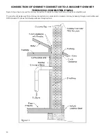
Page 10: ...ow to connect the chimney connector of a heater to a masonry chimney through a combustible wall There are five allowable ways that a chimney connector can be connected to a masonry chimney by passing through a combustible wall NFPA Standard 211 allows the following wall pass through systems Figure 11 ...

Page 11: ...ATTACH CONNECTOR SECURELY AIR SPACE inner surface of the chimney flue and shall be firmly cemented in place See Part A 2 Use a solid insulated listed factory built chimney length having an inside diameter of 6 and having 1 or more of solid insulation There must be at least a 9 air space between the outer wall of the chimney length and any combustible materials The inner end of the chimney length s...

Page 12: ... thermal conductivity of 1 0 Btu in ft F 4 88 kg cal hr m C or less 2 All clearances and thicknesses are minimums larger clear ances and thickness are acceptable 3 A chimney thimble as shown for 3 and 4 above Parts C and D shall be for types 3 and 4 connections to facili tate removal of the chimney connector for cleaning The chimney thimble shall be of ASTM C315 fireclay with 5 8 minimum wall thic...

Page 13: ...uired to lock feed door during firing sequence 4 Install the thermodisc on rear of furnace cabinet with the two screws provided Mount the conduit assembly from the junction box to the thermostat bracket Crimp the two female terminals to each of the wire leads Plug the wires to the thermodisc NOTE It does not matter which of the two wires plugs to which terminal on the thermodisc 5 Remove blowers f...

Page 14: ... wiring wires M1 M2 of one blower motor Wire leads from the distribution blower are usually BOTH BLACK Makes no difference which leads from the motor s connects to the corresponding leads coming out of the conduit Figure 16 WIRING DIAGRAM ...

Page 15: ...specificmodel Sealthesmokepipeinthechimneywithfurnacecement The chimney connector shall be securely supported and joints fastened with sheet metal screws or rivets e Install 8 diameter heat pipe to plenum of the central hot air furnace Use 26 gauge pipe and connectors to be purchased separately If central air conditioning is installed in the plenum install heat pipe above the air conditioning unit...

Page 16: ...this purpose and install the new gasket You may light up your stove again approximately24hoursafterhavingcompletedthisoperation This unit s ash door uses a 5 8 diameter rope gasket This unit s feed door uses a 1 2 diameter rope gasket SERVICE HINTS Do not expect a furnace to draw It is the chimney that creates the draft Smoke spillage into the house or excessive build up of water or creosote in th...

Page 17: ...el B Check length of flue pipe to chimney Your unit should be within six 6 feet of your chimney C Make sure chimney cap is not too close to the top of the chimney D Check chimney draft make sure chimney flue pipe is clean and chimney is of adequate height E Slide baffle should be pulled out prior to load door opening 4 Problem Distribution blower vibrating Solution A Tighten blower wheel to motor ...

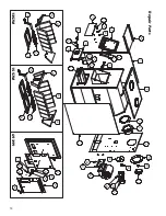
Page 18: ...18 Repair Parts 22 6 8 7 9 20 18 19 17 16 14 10 15 11 12 13 21 1 5 2 3 4 1 28 27 26 29 30 31 24 25 32 33 23 35 34 38 37 36 40 38 36 37 39 34 42 41 46 48 47 44 43 45 49 1357M 1557M 69399 ...

Page 19: ...wer 1357M 1 1557M 2 27 89319 Gasket Blower 1357M 1 1557M 2 28 83340 1 4 20 Clipnut 1357M 4 1557M 8 N S 83339 Bolt 1 4 20 x 3 4 1357M 4 1557M 8 29 22140 Relay Box Bracket 1 30 80131 Junction Box 4 x 4 1 31 80231 Junction Box Cover 1 32 80314 Thermodisc 60T12 1 33 68234 Blower Thermostat Bracket 1 34 89066 Firebrick 4 5 x 9 x 1 25 1357M 10 1557M 12 35 40264 Liner Front Rear 1357M 2 36 40256 Grate Fr...

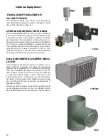
Page 20: ...uses a standard 16 x 20 x 1 filter NOT INCLUDED to reduce the amount of dust particles from being transfered thru you duct work system DR 6 BAROMETRIC DAMPER REGU LATOR In the unlikely event that your furnace overfires a con dition evidenced by elbows stove pipes and connectors glowing red in appearance or otherwise discoloring then your installation is subject to excessive draft cre ated by eithe...

Page 21: ...himney s or installations are going to be the same Just remember to allow enough air to enter the firebox and keep the stove pipe damper open so that volatiles are properly burned Before refueling take the time to break up the cone a little with a poker especially if it has caked over or formed a crust But be careful not to mix the coal as this increases the chances of forming clinkers When shakin...

Page 22: ...efueling If possible avoid shaking as a heavier layer of ash will help reduce the intensity of the fire during this time After loading let the fire establish itself for about 30 minutes Then close your damper and automatic control to the point where the house does not become too cold It is important that you begin banking early enough before retiring or leav ing that you can make necessary adjustm...

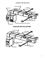
Page 23: ...23 CENTRAL INSTALLATION CENTRAL INSTALLATION ADD ON INSTALLATION ...

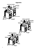
Page 24: ...AIR RETURN TOEXISTING DUCTWORK WARMAIR EXISTING FURNACE SOLIDFUEL FURNACE FILTERBOX PLENUM COLLECTOR BOX COLDAIR RETURN TOEXISTING DUCTWORK WARMAIR EXISTING FURNACE SOLIDFUEL FURNACE FILTERBOX COLDAIR RETURN PLENUMTOP OPTIONAL Appendix INSTALLATION A INSTALLATION B INSTALLATION C ...

Page 25: ...25 INSTALLATION D INSTALLATION E ...

Page 26: ...26 INSTALLATION F INSTALLATION G ...

Page 27: ...27 INSTALLATION H TOP VIEW FRONT VIEW ...

Page 28: ...ompany ________________________________________ Telephone No ______________________________________ Stove Inspected Chimney Swept Items Replaced ____________________________________ Service 05 Date ________________________ Engineer Name _____________________________________ Company __________________________________________ Telephone No ______________________________________ Stove Inspected Chimne...

Page 29: ... 4 Damage or defect caused by improper installation accidents misuse abuse including overfiring or alteration 5 Transportation or shipping costs LIMITATIONS AND EXCLUSIONS 1 United States Stove Company shall not be liable for incidental consequential special or contingent damages anyone might suffer as a result of their breach of this written warranty or any implied warranty 2 Should the heater be ...

Page 30: ...30 NOTES ...

Page 31: ...31 NOTES ...

Page 32: ...CHED TO THE HEATER WHEN ORDERING REPAIR PARTS ALWAYS GIVE THE FOLLOWING INFORMA TION AS SHOWN IN THIS LIST 1 THE PART NUMBER__________________________________ 2 THE PART DESCRIPTION______________________________ 3 THE MODEL NUMBER________________________________ 4 THE SERIAL NUMBER________________________________ United States Stove Company 227 Industrial Park Road P O Box 151 South Pittsburg TN 3...

Reviews: