


19
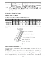
2) Move the control switch to the “ICE” position and check for proper control voltage. If
the “POWER OK” LED is on, the control voltage is good. If the “POWER OK” LED
is off, check the control transformer circuit. If no voltage is present, check the power
supply circuit.
3) To perform a relay sequence test, turn on the power switch while pressing the
"OUTPUT TEST" button. The correct lighting sequence should be 5, 6, 7, 8, 4. Some
components (e.g., the compressor) will cycle during test. Each LED comes on for
5 seconds. LED 5 is on while LED 6 is on. Following the output test sequence, the
icemaker will resume normal operation beginning with the 1 minute
fi
ll cycle.
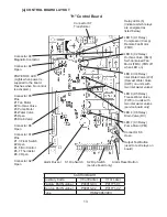
[e] CONTROL BOARD REPLACEMENT
The dip switches should be adjusted to the factory default settings as outlined in this
manual. If the S2 dip switch is mounted on the control board, all should be left in the “OFF”
position.
4. HARVEST CONTROL - THERMISTOR
A thermistor (semiconductor) is used as a harvest control sensor and anti-slush sensor.
The resistance varies depending on the suction line temperatures. The thermistor
detects the temperature of the evaporator outlet to start the harvest timer or momentarily
stop the pump motor during the freeze cycle. No adjustment is required. If necessary,
check for resistance between thermistor leads, and visually check the thermistor
mounting, located on the suction line next to the evaporator outlet.
Temperature (°F)
Temperature (°C)
Resistance (k
Ω
)
0
-18
14.401
10
-12
10.613
32
0
6.000
50
10
3.871
70
21
2.474
90
32
1.633
Check a thermistor for resistance by using the following procedure:
1) Disconnect the connector K1 on the board.
2) Remove the thermistor. See “V. 17. THERMISTOR”.
3) Immerse the thermistor sensor portion in a glass containing ice and water for 2 or 3
minutes.
4) Check for resistance between the thermistor leads. Normal reading is within 3.5 to 7
k
Ω
. Replace the thermistor if it exceeds the normal reading.
Summary of Contents for KM-61BAH
Page 16: ...11 ...
Page 30: ...25 2 WIRING DIAGRAM a KM 61BAH ...
Page 31: ...26 b KM 101BAH ...
Page 32: ...27 c KM 151BAH KM 151BWH ...
Page 83: ...78 Water Supply Inlet 1 2 FPT Drain Outlet 3 4 FPT Fig 34 KM 61BAH KM 101BAH KM 151BAH ...


