MAN0965-03-EN
Specifications/Installation
10/15/2013
No part of this publication may be reproduced without the prior agreement and written permission of Horner APG, LLC. Information in this document is subject to change without notice.
Page
3
of
6
4. NETWORK, POWER AND GROUNDING
A single, 5-pin connector is used to make both a network connection and power input. A quality, class-2 power supply should be
used for this product. If the power is run with the network cable, care must be taken such that the voltage does not drop below the
lower supply limit on longer runs. A separate supply for the controller and I/O is recommended for best noise immunity.
A quality earth ground is required for safe and proper operation. The best ground is achieved by screwing the lower left grounding
location into a grounded back plate. Alternately a ground can be connected to the spade lug.
Please see Horner manual MAN0799 for details on CAN wiring.
CAN Network & Power Connector
Torque rating 4.5 – 7 Lb-In (0.50 – 0.78 N-m)
CAN Network & Power Port Pin Assignments
Pin
Signal
Signal Description
Direction
1
V-
CAN and Device Ground - Black
2
CN_L
CAN Data Low - Blue
In/Out
3
SHLD
Shield Ground - None
4
CN_H
CAN Data High - White
In/Out
5
V+
Positive DC Voltage Input
(10-30VDC) - Red
5. CONFIGURATION
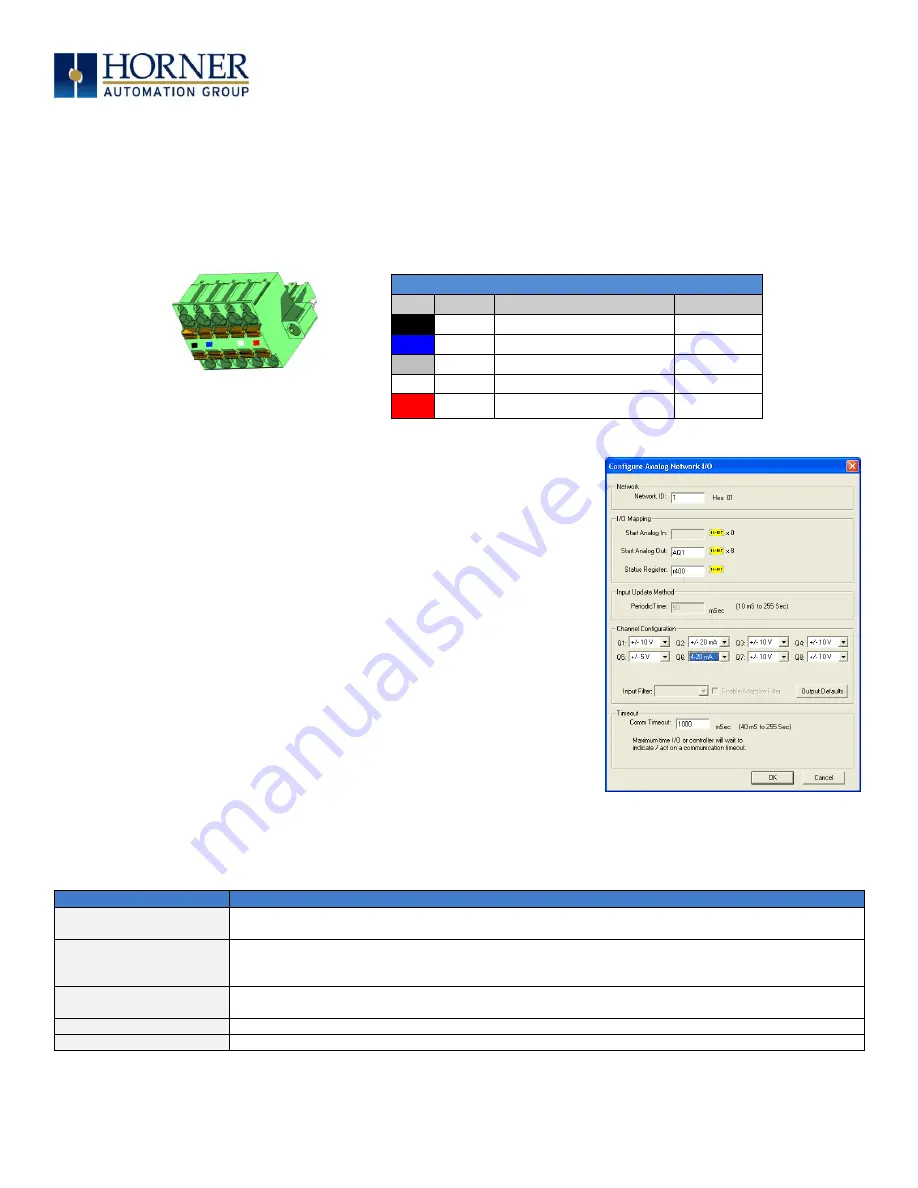
For most applications, the I/O scanner built into Cscape and the OCS firmware will
provide a fast, robust, and easy to use method to configure and scan the SmartBlock
I/O. For advanced operations, such as on-the-fly changes to the output type, please
see the following chapter on network data and the SmartStix and SmartBlock
programming guide.
To configure SmartBlock I/O from Cscape open the Hardware Configuration dialog
from the Controller | Hardware Configuration menu:
1. Select the option for
CsCAN I/O
.
2. Click
Add
.
3. Select the
SmartStix
Tab and select the device to be configured.
The DAC207 SmartBlock has the same configuration and network signature as the
SmartStix version. You can replace a SmartStix device with a SmartBlock in this
case with no programming changes. As of Cscape version 9.30, the configuration for
the DAC207 is found in the SmartStix tab. This will be added to the SmartBlock tab
in a future release for convenience.
To the right is the configuration for DAC207 device, configuration definitions are listed
below:
Configuration Type
Definition
Network ID
This should match the ID of the rotary switch on the SmartBlock unit and should be unique to the
network.
I/O Mapping
These registers define how the OCS controller registers are mapped to the data to and from the
SmartBlock I/O. These registers do not have to match the I/O types typically used for I/O such as %AI,
Q… Any standard controller registers may be used such as %R, %T and %M.
Input Update Method
This defines how often analog data is sent from the SmartBlock to the CsCAN network. Digital data is
transmitted on change of state.
Channel Configuration
This selects how each analog channel is configured including filtering.
Timeout
This sets the time a controller will wait before assuming the host OCS is off-line.


