PAGE 9 01 SEPTEMBER 1998 CHAPTER 2: INSTALLATIONS
HE500OCS050/051 User Manual
2.1.3
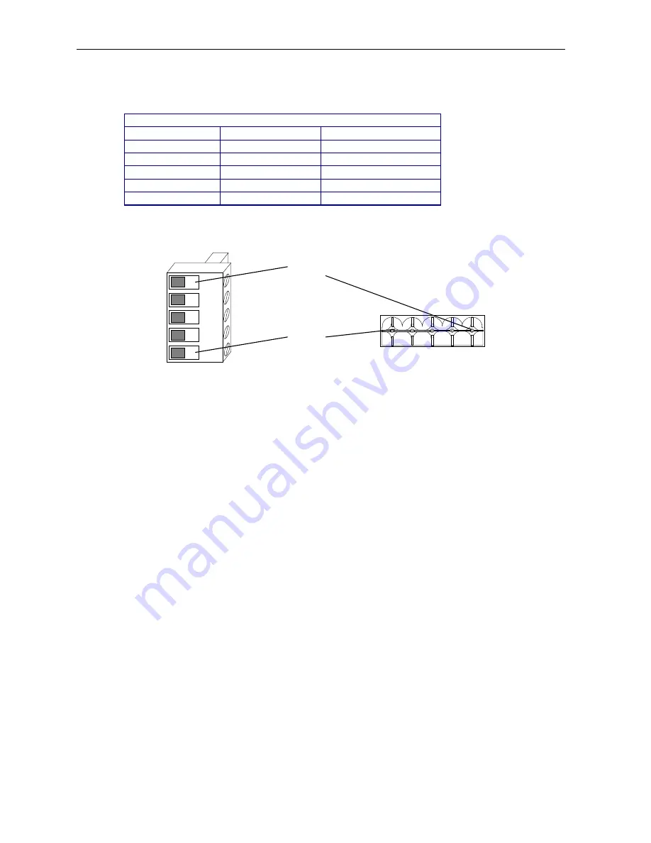
CAN Port
Table 2.2 – CAN Port Pinsc
Pin
Signal
Description
1
V+
CAN Power +
2
C+
CAN High
3
Shield
Shield
4
C-
CAN Low
5
GND
CAN Power Ground
a.
CAN Wiring Rules (See Figure 2.6.)
1.
A CAN network should be wired in a daisy-chained fashion such that there are exactly two
physical end-points on the network.
2.
The two nodes at the physical end-points should have 121 ohm 1% terminating resistors
connected across the CN_L and CN_H terminals.
3.
The data conductors (CN_L and CN_H) should be a 24 AWG shielded twisted pair for “thin cable”
and 22 AWG shielded twisted pair for “thick cable”, with 120 ohm characteristic impedance. Horner
Electric recommends using a Belden wire #3084A (“thin”) for typical industrial environments and a
#3082A (“thick”) for environments where noise is a concern.
4.
The power conductors (V- and V+) should be an 18 AWG twisted pair for “thin cable” and a 15
AWG twisted pair for “thick cable.”
5.
The V- power conductor should be connected to a good earth ground at one place only on the
network, preferably at one the two physical endpoints.
6.
Notice that for a section of cable between two nodes, the cable shield is connected to the cable
shield input at one end of the cable only.
7.
A CAN network (without repeaters) should be limited to 64 nodes (with 63 cable segments) with a
maximum cable length of 1500 ft.
8.
Up to four CAN network segments, which adhere to the above rules, may be connected together
using three CAN repeaters (HE200CGM100). In this manner, a CAN network may be extended to 253
nodes with a total cable distance of 6000 ft.
V +
C +
S hield
C -
V -
Pin 1
Pin 5
Figure 2.4 – Network Connector
Figure 2.5 – As viewed looking
(CAN Port) at the HE500OCS050/051


