


EN
Motor Service
WARNING:
Always disconnect the fl ight battery before performing
motor service.
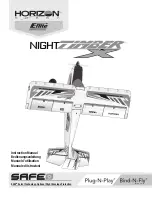
Disassembly
1. Remove the spinner screw (
A
) and spinner (
B
) from the propeller shaft (
C
).
2. Remove the spinner nut (
D
) by using an adjustable wrench.
3. Remove the propeller (
E
), back hub (
F
) and the propeller shaft from the
motor shaft.
4. Remove 2 screws (
G
) from inside the front cowling (
H
) and remove
the cowling from the fuselage.
5. Remove the 4 screws (
I
) and the motor (
J
) with the X-mount from the fuselage.
6. Disconnect the motor wires from the ESC wires.
7. Remove the 4 screws (
K
) and motor from the X-mount (
L
).
Assembly
Assemble in reverse order.
• Correctly align and connect the motor wire colors with the ESC wires.
• Install the propeller with the size numbers (13 x 4) facing out from the motor.
• Tighten the spinner nut to secure the propeller into place.
A
C
G
I
B
H
F
E
D
Wiring not shown
ring not shown
L
K
J
15
Post Flight
1. Disconnect the fl ight battery from the ESC (Required for Safety and
battery life).
2. Power OFF the transmitter.
3. Remove the fl ight battery from the aircraft.
4. Recharge the fl ight battery.
5. Repair or replace all damaged parts.
6. Store the fl ight battery apart from the aircraft and monitor the
battery charge.
7. Make note of the fl ight conditions and fl ight plan results, planning for
future fl ights.
PNP Receiver Selection and Installation
The Spektrum AR637TA receiver is recommended for ths airplane. If you
choose to install another receiver, ensure that it is at least a 5-channel full
range (sport) receiver. Refer to your receiver manual for correct installation and
operation instructions.
Installation
(AR637TA shown)
1. Remove the wing from the fuselage.
2. Mount the receiver parallel to the length of the fuselage as shown. Use
double-sided servo tape.
CAUTION:
Incorrect installation of the receiver could cause a crash.
3. Attach the appropriate control surfaces to the their respective ports on the
receiver using the chart in the illustration.
AR637TA Port
Assignments
BND/PRG = BIND
1 = Throttle
2 = Y-harness: Ailerons
3 = Elevator
4 = Rudder
5 = Lights
6 = Y-harness: Flaps
SAFE Select Flying
NOTICE:
If SAFE Select is active, a fl ap to elevator compensation can be
used to minimize pitch up when fl aps are deployed. However, do not use
throttle to elevator mix to reduce pitch up with fl aps deployed as the mix will
effect the high and low speed angles with fl aps deployed.
For a short takeoff, apply full throttle and hold up elevator until the desired
pitch attitude is reached. Continue holding up elevator until the appropriate
altitude is reached. Once the elevator stick is returned to center, the aircraft
will automatically resume level fl ight.
Alternatively, apply 1/2 to 3/4 throttle and let the tail come off the ground
naturally. Gently apply up elevator and allow the plane to approach the desired
altitude.
To land the aircraft, gradually decrease throttle and apply up elevator to adjust
your glideslope to the desired landing point. Just before you approach the
ground, reduce throttle to zero and fl are the aircraft.


