A
PPENDIX
Multi-Source Function System 7001RC - V02.01
31 / 31
hopf
Elektronik GmbH
Nottebohmstr. 41 • D-58511 Lüdenscheid • Tel.: +49 (0)2351 9386-86 • Fax: +49 (0)2351 9386-93 • Internet: http://www.hopf.com • E-Mail: [email protected]
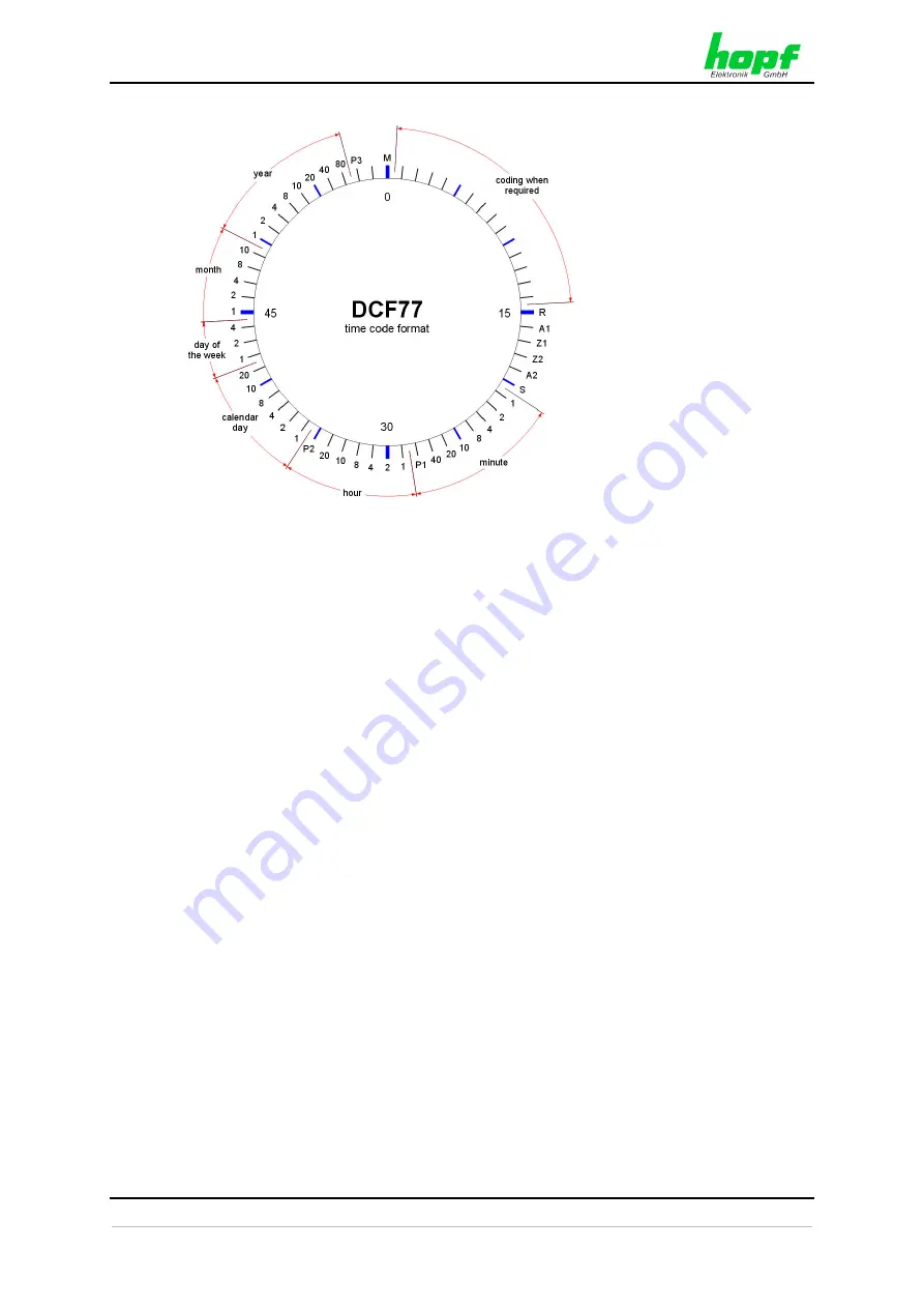
M
minute marker (0.1 s)
R
in the simulation this
bit is permanently set
to logic "0". In the
transmitted data string
via the DCF77
transmitter this bit
becomes logic "1"
when a spare antenna
is used for the
radiation.
A1
announcement
of
an
imminent changeover
from CET to CEST or
vice versa.
Z1, Z2
time zone bits
A2
announcement of a
leap second
S
initial bit of the coded
time information
P1, P2, P3
check
bits
DCF77 : D = German, C = Long wave signal, F = Frankfurt, 77 = frequency
3.2.2 DCF77 Pulse (1Hz)
The DCF77 pulse uses the same coding as the signal which is transmitted from the long
wave DCF77 transmitter in Frankfurt/Main. The difference is that no amplitude modulated
carrier signal is used for the transmission. The 100 and 200ms long lowering are showed
with logic signals.
3.2.3 Fault Mode
The DCF77 telegram is not output if the base system has no plausible time or is not radio
synchronous.
The output levels of the individual interfaces then remain in the idle position. This, however,
could also simulate a line break to the connected device.


