Honeywell GmbH
4
MU1H-1153GE23 R0911
GB
1. Safety Guidelines
1. Follow the installation instructions.
2. Use the appliance
• according to its intended use
• in good condition
• with due regard to safety and risk of danger.
3. Note that the appliance is exclusively for use in the
applications detailed in these installation instruc-
tions. Any other use will not be considered to comply
with requirements and would invalidate the
warranty.
4. Please take note that any assembly, commis-
sioning, servicing and adjustment work may only be
carried out by authorized persons.
5. Immediately rectify any malfunctions which may
influence safety.
2. Functional description
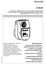
After the set time has expired, the Z74S-AN opens
the ball valve. In the filter, a differential pressure is
generated by this opening procedure, which in turn
starts the reverse rinsing mechanism. At the end of the
reverse rinsing interval, the ball valve closes again. An
additional safety function prevents the ball valve from
being opened if the battery voltage is too low. This
ensures that unwanted loss of water is avoided.
The end of the battery service life is indicated by the
flashing of the LEDs.
3. Application
For fully automatic reverse rinsing of Honeywell filters
F74CS, FN74CS and filter combinations FK74CS,
FKN74CS.
4. Technical data
5. Scope of delivery
The automatic reverse rinsing actuator consists of:
• Drive
• Power supply unit
• LR6 AA batteries (3 pcs)
6. Assembly
6.1 Installations Guidelines
• The installation site has to be frost-proof and the
protection of the device from chemicals, paints,
detergents, solvents and their vapours and environ-
mental influences must be guaranteed.
6.2 Assembly instructions
1. Close shut off valve on inlet and outlet
2. Open the ball valve on the filter by turning the
reverse rinsing knob
o The handle of the reverse rinsing knob must be
vertical
o Ensure proper water drainage or collection
container
3. Remove reverse rinsing knob on the filter
4. Remove battery protection strips and wait until the
drive stops turning
5. Flange-mount automatic reverse rinsing actuator
with bayonet joint
o Insert housing
o Press the housing against the ball valve in the
direction of the filter while holding from the other
side and turning the housing by 90°
6. Slowly open shut off valves on inlet and outlet
7. Set the desired reverse rinsing interval and wait until
the drive stops turning
6.3 Discharge of reverse rinsing water
The reverse rinsing water must be routed to the drain
channel in such a way that no backwater can occur.
To do this there are 3 options:
1. Direct connection:
o Connector DN 50/70 as well as the necessary
pipes and siphon (3 elbows 90°) in DN 70.
2. Discharge into floor drain
3. Drain into open container.
*at 4 bar inlet pressure and 20 seconds reverse rinsing duration
Medium
Water
Water temperature
Max. 30 °C
Ambient conditions
5...80% non-condensing,
0...40 °C
Reverse rinsing interval
adjustable to
1 hour / 1 day / 6 days /
15 days / 30 days / 45 days /
2 months / 3 months
Open/closing time
20s
Supply voltage
• Battery operation
• Power supply unit
4.5V DC +5/-20%
3 AA batteries
1.5 volt, LR 6 (alkali manga-
nese)
230V/50Hz – 6V/500mA
Battery display
LED – flashes when voltage
is under 3.6V
Protective class
IP42
Discharge lines are to be implemented
according to DIN EN 806.
Filter size
Discharge
connection
Reverse rinsing
volume*
1/2" and 3/4" DN 50
10 litres
1" and 1 1/4" DN 70
12 litres
Reverse rinsing duration, approx. 20 s.


