background image

WT8840 TRADE WATER HEATER CONTROLS

7

34-00013EF—01

Troubleshooting Without Status Indicator Assistance

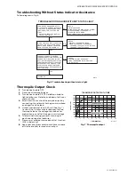
Follow diagram in Fig. 6.

Fig. 6. Troubleshooting without status light.

Thermopile Output Check

1.

Turn device knob to OFF.

2.

Disconnect thermopile leads.

3.

Turn device knob to PILOT, hold down knob to 
light pilot burner. Hold the knob down for five or 
more minutes.

4.

After five minutes, check thermopile output by 
connecting the voltmeter to the positive red lead 
and negative white lead.

5.

Output should be at least 350 mV. (See Fig. 7.) 
Connect the 3.6 ohm resistor between the two 
thermopile leads, the voltage should be at or 
higher than one half of the open circuit voltage.

6.

The terminal housing prevents miswiring of 
positive and negative leadwires.

7.

Flame must envelop thermopile at Hot Junction 
(3/8 in. below tip).

8.

Keep heat away from cold junction (brass sleeve 
of the thermopile) for maximum output.

Fig. 7. Thermopile output.

TURN DEVICE KNOB FROM OFF TO 

PILOT, PRESS DOWN KNOB AND HOLD, 

LIGHT PILOT BY DEPRESSING PIEZO 

IGNITION BUTTON, PILOT SHOULD 

LIGHT.

–  WATER TEMPERATURE IS BELOW 

  THE CUT-OUT LIMIT

CHECK:

• WIRING OF THERMOPILE LEADS

• FLAME COVERAGE OF THERMOPILE

   – THERMOPILE OUTPUT IS TOO LOW-RUN 

     THERMOPILE OUTPUT CHECK

STATUS LIGHT SHOULD FLASH AFTER  

1 MINUTE, LED WILL FLASH NORMAL  

SINGLE BLINK, RELEASE THE DEVICE  

KNOB, PILOT SHOULD REMAIN LIT 

TURN DEVICE KNOB TO DESIRED

TEMPERATURE SETTING, BURNER WILL

TURN ON ONLY IN ACTIVE CALL FOR

HEAT (WATER TEMPERATURE IS LESS 

THAN TEMPERATURE SETTING MINUS 

DIFFERENTIAL); LED FLASHES 1 TIME 

EVERY 3 SECONDS WHILE IDLE AND 

STROBES EVERY 3 SECONDS DURING 

A CALL FOR HEAT.

SYSTEM OK

CHECK:

• EXCESSIVE INLET PRESSURE

• TANK TEMPERATURE IS AT OR CLOSE

  TO SET POINT

NO 

NO 

NO 

YES

YES 

YES

M29431

TROUBLESHOOTING GUIDE WITHOUT STATUS LIGHT 

CHECK:

• INLET PRESSURE

• MAKE SURE AIR IS BLED OUT OF SYSTEM

• PIEZO SPARKING TO THERMOPILE

• CLOGGED PILOT ORIFICE

• GAS LEAK IN PILOT TUBING CONNECTIONS

M22535B

TIME (MINUTES)

OUTPUT (mV)

THERMOPILE OUTPUT WITH TIME

500

600

400
300
200
100

0

0

1

2

3

4

5

6

7

8

9

10

900
800
700

NORMAL RANGE

OUTPUT TOO LOW

Summary of Contents for WT8840

Page 1: ...ressure range recommendation 0 5 PSI 14 0 in w c maximum inlet pressure allowed for proper operation Body Pattern 90 degrees with 1 2 in inlet and 1 2 in inverted flare outlet Mounting Mounting in upright position only Control Input Voltage Minimum 350 mV dc open circuit Voltage Maximum 850 mV dc open circuit Capacity See Table 1 Regulation Range Natural Gas Minimum 30 000 Btuh Maximum 85 000 Btuh...

Page 2: ...ded in air as in some industrial or agricultural applications protect the control with a cover Dust or Grease Accumulation Heavy accumulations of dust or grease can cause the control to malfunction Where dust or grease can be a problem provide covers for the control to limit contamination Heat Excessively high temperature can damage the control Make sure the maximum ambient temperature at the cont...

Page 3: ...es 1 Use a new properly reamed pipe free from chips If tubing is used make sure the ends are square deburred and clean All tubing bends must be smooth and without deformation 2 Ensure that gas supply is turned off 3 Run pipe or tubing to the water heater control If tubing is used obtain a tube to pipe coupling to connect the tubing to the control 4 Install a sediment trap in the supply line to the...

Page 4: ...feet of 1 2 in pipe with 5 in w c pressure 2 Depress the piezo igniter to light the pilot flame and hold the knob in until the status indicator starts to blink approximately 30 seconds indicating pilot now being held by electronics NOTE LED should blink once every three seconds If not check the error codes in Table 3 3 Release the knob and turn to the desired temperature setting The burner will co...

Page 5: ...s Leak Test at plug with main burner operating Procedure to check the gas input and burner flow rate 1 Check the full rate manifold pressure listed on the appliance nameplate Water heater control full rate outlet pressure should match this rating 2 With burner operating check the water heater control flow rate using the meter clocking method or check pressure using a manometer connected to the out...

Page 6: ...Normal operatio n No action required 1 flash every 3 seconds Not an error indicates the electronics is holding the Pilot Valve open and the Main Valve closed You can now turn the knob to a desired setpoint temperature LED will continue to flash 1 time every 3 seconds while in Idle mode no call for heat Strobe every 3 seconds Not an error indicates call for heat during normal operation Main valve o...

Page 7: ...DEVICE KNOB FROM OFF TO PILOT PRESS DOWN KNOB AND HOLD LIGHT PILOT BY DEPRESSING PIEZO IGNITION BUTTON PILOT SHOULD LIGHT WATER TEMPERATURE IS BELOW THE CUT OUT LIMIT CHECK WIRING OF THERMOPILE LEADS FLAME COVERAGE OF THERMOPILE THERMOPILE OUTPUT IS TOO LOW RUN THERMOPILE OUTPUT CHECK STATUS LIGHT SHOULD FLASH AFTER 1 MINUTE LED WILL FLASH NORMAL SINGLE BLINK RELEASE THE DEVICE KNOB PILOT SHOULD R...

Page 8: ... heated water IMPORTANT Follow the operating instructions provided by the manufacturer of your water tank appliance The information in this form describes a typical water heater control application but the specific controls used and the procedures outlined by the manufacturer of your appliance can differ requiring special instructions STOP READ THE WARNINGS ABOVE If the appliance does not turn on ...

Reviews: