


WEB/CP-202-XPR AND WEB/CP-602-XPR CONTROLLERS
3
95-7775—01
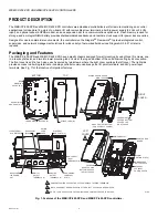
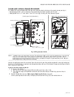
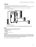
The wiring area under the right cover provides knockouts at the back, bottom and top holes, and a grounding terminal strip. For
wiring ease, the controller uses removable screw terminal blocks, using 0.2 in. (5mm) spacing. Typically, the left-side cover needs
removal only if replacing the NiMH battery pack, installing a SIM card in the onboard GPRS modem (if model so equipped), or if
installing an option card on the controller. One option card is supported, to provide additional communications, e.g. LonWorks
®
FTT-10, or another RS-232 port. Controller models are available with a pre-installed GPRS modem, which does not consume the
option card slot.
Sixteen (16) integral I/O points include eight (8) universal inputs (UIs), compatible with 0 to 10 Vdc, 4 to 20 mA, dry contacts,
pulsing dry contacts, or Type 3 thermistor sensors. Four (4) digital outputs with Form-A relay contacts provide on/off control of
loads up to 30 Vac or Vdc, at 0.5A maximum. Four (4) 0 to 10 Vdc analog outputs provide analog control of loads at 2.5K ohm
minimum, or 4 mA drain maximum.
Ten (10) LEDs are visible atop the left cover, indicating the state of each of the four digital outputs, along with the status of the
controller, Ethernet, and wireless options (if installed). For GPRS equipped models, a GSM/GPRS quad-band antenna can be
mounted on the left side. A rechargeable NiMH battery pack is included inside the unit. Separate terminals support an external
12 V sealed lead-acid (SLA) backup battery, if desired.
The controllers use a PowerPC processor with Flash memory for storage and have either SDRAM or DDR RAM. TCP/IP access
is via two standard Ethernet ports, and two serial ports (RS-232, RS-485) are also standard. The controllers use the QNX
®
RTOS
operating system, along with the IBM J9 JVM. For a complete listing, see the next section “Technical Specifications.”
Technical Specifications
WEB/CP-202-XPR and WEB/CP-602-XPR Platforms
• WEB/CP-202-XPR models:
— PowerPC 405EP @ 250 MHz processor.
— 128 MB SDRAM and 64 MB Serial Flash.
• WEB/CP-602-XPR models:
— PowerPC 440 @ 524 MHz processor.
— 256 MB DDR RAM and 128 MB Serial Flash.
• Real-time clock.
• Two (2) Ethernet ports; 10/100 Mbps with RJ-45 connectors.
• One (1) RS-232 port using an RJ-45 connector.
• One (1) isolated RS-485 / 15 Vdc power on a 6-position connector. Usable as a standard non-powered isolated RS-485 port
on 3 terminals, or to support remote I/O modules – available in a later release.
(A
maximum of three
IO-16-REM-H modules on the WEB/CP-202-XPR controller is recommended, due to platform resource
considerations).
• One (1) available comm option card slot for a communications option card, such as LonWorks FTT-10, an additional RS-232
port, or two more isolated RS-485 ports.
• One (1) USB port for future use (WEB/CP-602-XPR models only).
• LEDs on front of unit to monitor controller power, system status, and digital output states.
Onboard I/O Points
• 16 total points of I/O, using removable screw terminals with spacing of 0.2 in. (5mm) centers for all inputs and outputs, in
connector blocks of 6 or more screws each.
• 8 Universal Inputs (UI), with the following types supported:
— Type 3 (10K) Thermistors; Thermistor Sensor Range -23.3 to 115.5°C (-10 to 240°F).
Input accuracy is in the range of ± 2% of span. Other types may be supported by entering custom non-linear curve inter-
polation points for each unique non-linear input.
— 0 to 10 Vdc; accuracy is ± 2% of span, without user calibration.
— 4 to 20 mA current loop; accuracy is ± 2% of span, without user calibration. Self-powered or board-powered sensors
accepted; uses an external resistor for current input (four provided, mounted by installer on input terminal connections).
— Dry contact; 3.3 V open circuit, 300 uA short-circuit current.
— Pulsing dry contact, at rate up to 20 Hz; 50% duty cycle.
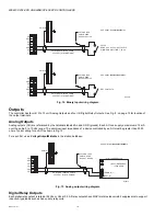
• 4 Digital Outputs (DO), using Form A relay contacts; suitable for on/off control only (no floating control). Maximum load voltage
is 30 Vdc or Vac; with 0.5 A maximum current rating per contact.
• 4 Analog Outputs (AO), providing 0 to 10 Vdc signal, at 4 mA drain maximum (controlled load must have resistance of
2500 ohms or higher).


