


WEB/CP-202-XPR AND WEB/CP-602-XPR CONTROLLERS
95-7775—01
2
PRODUCT DESCRIPTION
The WEB/CP-202-XPR and WEB/CP-602-XPR controllers are embedded controller/servers for remote monitoring and control
applications. Included are 16 points of on-board I/O with removable screw terminals, a built-in power supply (24 Vac or 24 Vdc
input), an optional onboard GPRS modem, and one expansion slot for a communications option card. Flash memory is used for
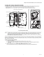
storage, and an integral NiMH battery provides shutdown/database backup and real-time clock support for power loss scenarios.
Designed for use in commercial environments, the controllers run the Niagara
AX
Framework
®
to provide integrated control,
supervision, and network management solutions for wide variety of networked field devices. NiagaraAX-3.4.51 or later is
required.
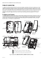
Packaging and Features
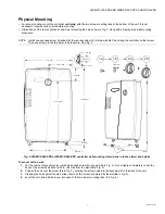
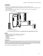
The WEB/CP-202-XPR and WEB/CP-602-XPR have a plastic chassis designed for wall mounting by using three (3) screws; one
in a rear keyhole slot, and two into lower mounting tabs. Vents at the top and bottom of the unit allow cooling by air convection.
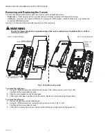
The front cover is split in two halves, each secured by two screws, where the right cover overlaps the left cover. The right side
provides access to all wiring terminals, including controller communications ports, I/O point terminals, and 24V power input
terminals. See Fig. 1 for the location of important features.
Fig. 1. Features of the WEB/CP-202-XPR and WEB/CP-602-XPR controllers.
M29983
WIRING AREA IS UNDER
RIGHT COVER
KNOCKOUTS AT BOTTOM
(2; ONE FOR 24V POWER)
2 SCREWS AT
TOP AND BOTTOM
SECURE THE
RIGHT COVER
CONTROLLER
BOARD
COMM
OPTION SLOT (1)
NIMH BACKUP
BATTERY PACK
INTEGRAL
24V INPUT
POWER SUPPLY
2 SCREWS
NEAR TOP AND
BOTTOM SECURE
THE LEFT COVER
LEFT
COVER
GROUNDING
TERMINAL
STRIP
UNIVERSAL
INPUT
TERMINALS (8)
RS-485 AND
15V POWER
OUT
DIGITAL
OUTPUT
TERMINALS (4)
ANALOG
OUTPUT
TERMINALS (4)
RIGHT
COVER
REAR
MOUNTING
KEYHOLE (1)
REAR WIRING
KNOCKOUTS (6)
STATUS LEDS (10)
LOWER MOUNTING TABS (2)
BOTTOM
TOP
REMOVABLE SHIELD COVERS THE 24V POWER INPUT WIRING TERMINALS.
1
1
SIM CARD SLOT
2
2 RIGHT COVER MUST BE REMOVED FIRST, THEN LEFT COVER CAN BE REMOVED.
3 SEE FIG. 15 ON PAGE 22 FOR I/O TERMINALS AND CONTROLLER PORTS DETAILS.
12V EXTERNAL
SLA BATTERY
RS-232 PORT
(RJ-45)
OPTION
CARD
AREA
ETHERNET
LAN PORTS (2)
3


