


WEB/CP-202-XPR AND WEB/CP-602-XPR CONTROLLERS
25
95-7775—01
Backup Battery
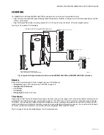
The optional sealed lead-acid backup battery is an external, 12V, rechargeable battery (or multiple batteries) sized to operate the
system during loss of primary power for some duration, typically four (4) hours. The current load includes the controller, as well as
power to attached remote I/O expansion modules.
Connect the backup battery to the controller using a 2-position connector (see Fig. 16 on page 22).
Whenever primary-powered, the controller supplies a constant “trickle” charge to this battery, at 200mA maximum.
NOTE: Use the 712BNP Sealed Lead Acid Backup Battery.
Providing the controller platform is so configured, at startup (boot), a test of the backup battery is performed, as well as a periodic
test. A system alarm is generated if a battery test deems the backup battery to be bad. If the backup battery has tested good,
upon loss of primary power the system operates from this backup battery power until the charge level of the on-board NiMH
battery pack reaches 0. Note that both batteries discharge in parallel. However, as the sealed lead-acid backup battery capacity
is much greater, the NiMH battery pack discharges much slower than if these backup batteries were bad or not present.
NOTE: If the backup battery test was “bad,” upon loss of primary power, the controller performs an immediate shutdown,
backing up data and powering off (including expansion modules).
Replace the sealed lead-acid backup batteries approximately every three (3) years, or more often if the unit is in a high
temperature environment.
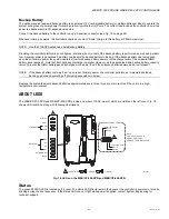
ABOUT LEDS
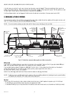
The WEB/CP-202-XPR and WEB/CP-602-XPR provide a number of LEDs, most of which are visible on the left cover. Fig. 18
shows LED locations, along with following descriptions.
Fig. 18. LEDs on the WEB/CP-202-XPR and WEB/CP-602-XPR.
Status
The green STATUS LED is located on the cover. The status LED should remain lit whenever the controller is
powered
, or else be
blinking during the boot sequence. If the status LED
does not light
while power is applied, contact System Engineering for
technical support.
1
SERIAL PORT LEDS
STATUS
BEAT
PRI
SEC
ETHERNET
RELAY OUT
(FUTURE USE)
K4
K3
K2
K1
GPRS
COM1 (RS-232)
S1TX
S1RX
NOTE:
TO CHECK THE FOUR
SERIAL PORT LEDS,
REMOVE THE RIGHT COVER.
COM2 (RS-485)
S1TX
S1RX
1
1
M28881
LED COLORS: = GREEN, = YELLOW


