background image

SP970A, B, C AND D MANUAL AND MINIMUM POSITION PRESSURE REGULATORS 

BEFORE INSTALLATION 

SP970A and C only 

For panels having a thickness greater than 5/16 in. 
(8 mm) but less than one in. (25 mm), use 315677A Bus 

Assembly. 

INSTALLATION 

Mounting 

The SP970A and C can be panel, surface or wall 
mounted. The SP970B and D are surface or wall 

mounted. See Fig. 3 and 4. 

20 

40 

60  80 

1

0

5/8 IN. (16MM) 
DIA. HOLE 

SCALEPLATE 

SHAFT

SP97O 

HEX NUT 

CENTER 

PUNCH 

MARK 

IN "V" 

GROOVE 

PANEL-UP TO 5/16 IN. 
(8MM) THICK 

HEX NUT 

KNOB 

CENTER PUNCH MARK IN "V" GROOVE 
SHOWING 8 PSI (55 kPa) CALIBRATION -
ENLARGED 

8 PSI 

C8278 

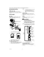
Fig. 3. SP970A and C panel mounting. 

SP970A AND C 

SP970B AND D 

SP970 SWITCH 

MOUNTED 

HERE 

SPRING 
CLIP 

SCREW 

C8275 

C8277 

80 

60

40 

20 

1

0

Fig. 4. SP970 surface or wall mounting. 

Panel Mounting SP970A and SP970C 

1.


Drill a 5/8 in. (16 mm) hole. 

2.


Lock the SP970 switch and scaleplate to the panel 
with a hex nut on the back of the panel. Use a sec-

ond hex nut on the front panel. See Fig. 3. 

NOTES: 

√ 

The scaleplate, knob and two mounting nuts 

are furnished with SP970A and C. 


Do not mount the knob during installation. 

Refer to the Calibration section of this docu-
ment. 

Surface Mounting 

Use the mounting bracket as a template and secure 

mounting bracket to surface. See Fig. 4. Screws are not 
provided. 

Piping 

All connections are sharp barb 5/32 in. (4 mm) O.D. 

polyethylene tubing. 

CAUTION 

Equipment Damage Hazard. 

To prevent damage to the sharp barb 

connections, do not attempt to cut or pull tubing. 
To remove the tubing from the barb connections, 

cut tubing a few inches from the control device. 
Use a coupling to reconnect tubing. 

NOTES: When the system is not copper or polyethylene 

tubing, adapt as shown in Fig.5. Some models 
provide parts for adapting. 

5/32 IN. (4 MM) O.D. 
PLASTIC TUBING 

5/32 IN. (4 MM) 
O.D. PLASTIC 
TUBING CUT 
TO LENGTH 

5/32 IN. X 1/4 IN. 
(4 MM X 6 MM) 

O.D. PLASTIC

 CONNECTOR 
(CCTI606B) 

CONNECT

 1/4 IN. 

1/4 IN. (6 MM)

(6 MM) 

O.D. PLASTIC 

COPPER 

TUBING CUT TO
 LENGTH 

1/4 IN. (4 MM) O.D. 
PLASTIC/COPPER 
ADAPTER 
(CCTI633BT) 

1/4 IN. (6 MM) O.D. 
COPPER TUBING 

C8276 

Fig. 5. Adaptation piping. 

Port Identification Table 

The two right columns in Table 1 identifies the ports of 
older Honeywell pneumatic relays when upgrading 

installation. 

SP970A-D 

POST FOR 

CONNECT

 1/4 IN.

 (6 MM)

 PLASTIC 

95-7237EF


Summary of Contents for SP907B

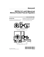
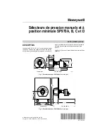
Page 1: ...inimum Position Pressure Regulators provide regulated pressure to a Figs 1 and 2 show approximate dimensions SP970A 3 1 2 89 SP970C 3 7 8 98 0 8 0 60 40 2 0 10 0 2 1 2 63 1 1 2 38 7 8 22 2 1 4 57 1 7 8 48 C4857 FRONT VIEW SIDE VIEW Fig 1 SP970A and C dimensions in in mm 3 1 2 89 0 8 0 60 40 2 0 10 0 3 1 4 83 2 1 16 62 1 9 16 40 1 25 7 8 4 1 2 114 FRONT VIEW 22 SIDE VIEW C4858 Fig 2 SP970B and D di...

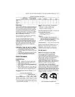
Page 2: ...nished with SP970A and C Do not mount the knob during installation Refer to the Calibration section of this docu ment Surface Mounting Use the mounting bracket as a template and secure mounting bracket to surface See Fig 4 Screws are not provided Piping All connections are sharp barb 5 32 in 4 mm O D polyethylene tubing CAUTION Equipment Damage Hazard To prevent damage to the sharp barb connection...

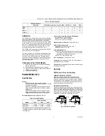
Page 3: ... chamber for minimum pressure applications mounted on a sheet metal panel Selectable Spans for psi kPa See Table 2 Table 2 Selectable Spans Model Knob Rotationa 188 244 300 Small span 5 34 6 5 45 8 55 Large span 10 69 13 90 16 110 a The setpoint knob normally rotates 188 degrees Two breakaway stops on the knob allow rotation of 244 and 300 degrees Operating Pressure Switch and Pilot Range Normal M...

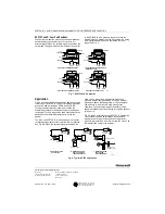
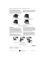
Page 4: ...es the damper The three port SP970A B is also used with a controller for automatic damper positioning with minimum position See Fig 8B When the external signal is less than the knob setting the spring maintains the branchline pressure as previously described When the external signal rises above the knob setting air from the signal flows directly to the branch During steady state conditions the ext...

Page 5: ...Les Fig 1 et 2 donnent l encombrement approximatif des servomoteurs pneumatiques de registres Ils servent à appareils SP970A 89 3 1 2 SP970C 98 3 7 8 0 8 0 60 40 2 0 10 0 63 2 1 2 38 1 1 2 22 7 8 57 2 1 4 48 1 7 8 CF4857 VUE DE FACE VUE DE PROFIL Fig 1 Encombrement des SP970A et C en mm po CF4858 89 3 1 2 0 8 0 60 40 2 0 10 0 83 3 1 4 62 2 1 16 40 1 9 16 25 1 22 7 8 114 4 1 2 VUE DE FACE VUE DE PR...

Page 6: ...t de l installation Consulter la section Étalon nage de la présente notice technique Montage en surface Utiliser le support de montage comme gabarit puis le fixer à la surface Voir la Fig 4 Les vis ne sont pas fournies Tuyaux Tous les raccords sont effectués avec des tuyaux à crans en polyéthylène de 4 mm 5 32 po de diam ext MISE EN GARDE Risque de dommage matériel Ne pas couper ni tirer les canal...

Page 7: ...ure en kPa psi voir le Tableau 2 Tableau 2 Choix d intervalles Gamme de pression de service commutation et pilote Canal princ normale 124 kPa 18 psi Canal sec 21 à 103 kPa 3 à 15 psi Pilote 21 à 103 kPa 3 à 15 psi Pression d air admissible maximale 207 kPa 30 psi Limites ambiantes de service Température 18 à 60 C 0 à 140 F Humidité relative 5 à 95 Débit d air SP970A B au dessus de la position mini...

Page 8: ...e la pression dans la canalisation secondaire et le registre se ferme Les appareils SP970A et B à trois orifices sont aussi utilisés avec des régulateurs pour positionner automatiquement un registre en position minimale Voir la Fig 8B Lorsque la pression du signal extérieur est inférieure à celle du réglage du bouton le ressort maintient la pression dans la canalisation secondaire comme il est déc...

Reviews: