W5054B_DE_1206 Seite 9/13
PEHA Lichtsteuerung – PEHA Elektro GmbH & Co. KG a Honeywell Company · Gartenstraße 49 · 58511 Lüdenscheid · Deutschland · www.peha.de · [email protected]
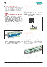
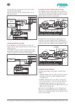
As shown below, one or more luminaires may be connected to
each channel of the D CDH8U5.
Note: For the maximum number of allowable ballasts, refer to
Technical Data section.
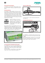
Connecting Switched Live Output
The D CDH8U5 has 7 switched live outputs. As shown in the
diagram below, the Neutral and Earth connections should be taken
directly to the load.
Each Switched Live output is rated for a load of up to 6A, with a
total maximum switched live load not exceeding 16A for the unit.
Output 8 is provided as a volt-free style for extra flexibility.
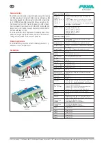
Connecting Volt Free and Maintained Live Output
The D CDH8U5 provides a 5-way terminal block for connecting
mains rated Volt Free load and maintained Live Output. For wiring
convenience, the middle terminal of the 5-way block is internally
linked to the Mains Live input as shown below.
The diagram below shows Maintained Live generated from the
internal link of the mains supplied to the unit. Alternatively, the
external shorting link can be removed and an external supply (from
the same phase) can be connected to create a Maintained Output.
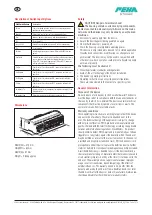
Connecting Presence Detectors
The following SELV detectors are designed to interface to the D
CDH8U5:
• D MLS2500CDRR4 Corner-mount Microwave presence detector
with photocell, semi-flush mounted. Available with surface
mount (SM suffix).
• D MLS2001CDR 360° PIR presence detector with photocell,
flush mounted. Available in surface mount version (SM suffix).
• D MLSM2002CDR Controller for a 360° PIR detector with
photocell. Used with the D DHS or D DHW mini-head to form an
integral luminaire-mounted unit.
Each connects to the D CDH8U5 by means of an Ethernet-style
RJ45 connector terminated patch lead which are available ready-
made in 2m, 3m, 5m and 10m lengths. Up to five detectors may be
connected to a D CDH8U5.
Note: + and -
relevant for
analogue
versions only.
MAINS INPUT
SWITCHED LIVE OUTPUTS
VOLT FREE CHANNELS
N
L
3
4
2
1
5
6
8
7
7
LIVE
ML
DIMMING CHANNELS
MLS
8
7
6
5
4
3
2
1
1
2
1
2
Ballast
Ballast
N
N
L
L
E
E
D
D
D
D
L1
L
E
E
N
N
SELV SWITCH INPUTS
DETECTOR PORTS
12
11
10
9
8
5
4
3
2
1
B A B A
B A B A
B A
B COM A
B COM A
B COM A
B COM A
B COM A
5
4
3
2
1
N/C COM N/O
AUX 1
Loads on Channel 1
MAINS INPUT
SWITCHED LIVE OUTPUTS
VOLT FREE CHANNELS
N
L
3
4
2
1
5
6
8
7
7
LIVE
ML
DIMMING CHANNELS
MLS
8
7
6
5
4
3
2
1
1
2
1
2
Ballast
N
L
E
L1
L
E
E
N
N
SELV SWITCH INPUTS
DETECTOR PORTS
12
11
10
9
8
5
4
3
2
1
B A B A
B A B A
B A
B COM A
B COM A
B COM A
B COM A
B COM A
5
4
3
2
1
N/C COM N/O
AUX 1
MAINS INPUT
SWITCHED LIVE OUTPUTS
VOLT FREE CHANNELS
N
L
3
4
2
1
5
6
8
7
7
LIVE
ML
DIMMING CHANNELS
MLS
8
7
6
5
4
3
2
1
1
2
1
2
Switched Live
Internal Link
SELV SWITCH INPUTS
DETECTOR PORTS
12
11
10
9
8
5
4
3
2
1
B A B A
B A B A
B A
B COM A
B COM A
B COM A
B COM A
B COM A
5
4
3
2
1
N/C COM N/O
AUX 1
Maintained
Output
External
Shorting
Links
MAINS INPUT
SWITCHED LIVE OUTPUTS
VOLT FREE CHANNELS
N
L
3
4
2
1
5
6
8
7
7
LIVE
ML
DIMMING CHANNELS
MLS
8
7
6
5
4
3
2
1
1
2
1
2
Switched Live
Internal Link
SELV SWITCH INPUTS
DETECTOR PORTS
12
11
10
9
8
5
4
3
2
1
B A B A
B A B A
B A
B COM A
B COM A
B COM A
B COM A
B COM A
5
4
3
2
1
N/C COM N/O
AUX 1
Live in from
same Phase
Maintained
Output
External
Shorting
Link
GB


