W5054B_DE_1206 Seite 11/13
PEHA Lichtsteuerung – PEHA Elektro GmbH & Co. KG a Honeywell Company · Gartenstraße 49 · 58511 Lüdenscheid · Deutschland · www.peha.de · [email protected]
Commissioning
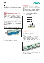
The LCM is commissioned using a dedicated programme running
on a Windows-based computer. Commissioning settings may then
be directly uploaded from the computer to the LCM or transferred
to an D HP2000 hand-held programmer for easy upload on site.
Communication from the PC can be by means of a USB infrared
transceiver which can signal directly to the LCM’s on-board infra-
red port over a short range or via any attached presence detector
from beneath (range: 1-3m).
The main parameters for configuration are tabulated below. These
parameters may be re-programmed any number of times and all
settings will be retained in the event of a power loss.
Product Applications
The D CDH8U5 may be used in various different applications, e.g.
warehouse, school, hospital, hotel.
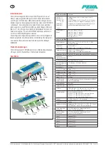
Connections
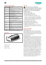
Parameter per Box
Options
Switch A: 1-5
Switch B: 1-5,
Switch 6A*, 6B*, 7A*, 7B*
Switch A: 8-12,
Switch B: 8-12
*
Planned
User may choose any option for Switch A or Switch B from
following:
Sustain / Brighten / Dim / Off / Scene 01..06 / On / Partition /
OneSwitch / On-Dim / Off-Brighten / On-Brighten / Off-Dim /
Emergency Test / Emergency End (See separate table for detailed
description of Switch Input options)
Detector 1-5: Range
Max 100%, Max 75%, Max 50%
High 100%, High 75%, High 50%
Med 100%, Med 75%, Med 50%
Low 100%, Low 75%, Low 50%
Min 100%, Min 75%
Parameter per Channel Options
Ballast Type
Non-Dimming, 1 % DSI, 3 % DSI, 10 % DSI, 1 % DALI,
3 % DALI, 10 % DALI
Assigned Detectors
Detectors 1-5: Assigned or not assigned to this channel
Assigned Photocell
Photocell 1-5 (in Detectors 1-5): Assigned or not assigned to
this channel
Assigned Switches
Switch A & B: Assigned or not assigned to this channel
Power Up
On / Off
Response
Auto, Manual/Bus, Manual Only
Main Time Delay
(Off Delay)
10 seconds to 96 hours, 20 minutes
Bus Connect
Yes / No
Zones 1-4
Zone Number 1-100
Corridor 1-2: Begin
Zone Number 1-100
Corridor 1-2: End
Zone Number 1-100
Global 1-2 Rx
Yes / N0
Manual I/P (Local/
Share for Each Switch)
Obey locally only / Obey locally and transmit command on
MLS bus
Start Lamps
Max / Min
Entry Scene
Scene 1-6
Lamp Max
100%, 90%, 80%, 70%, 50%, 45%, 40%, 35%, 30%, 25%,
20%, 15%, 10% Note: Not required for VF or SELV Outputs
When Vacant
(Turn-Off Options)
Off until next occupancy detection
Minimum, 25% or Scene 6 until next occupancy detection
Minimum, 25% or Scene 6 for 3 x Off Delay
Minimum, 25% or Scene 6 until the building is empty
Fade to Off
Yes / N0 Note: Not required for VF or SELV Outputs
Bright Out
Yes / N0
Photocell
Regulate (100%, 90%, 80%, 70%, 60%, 50%) / Passive /
Active / Disabled Note: Not required for VF or SELV Outputs
Photocell Lower
Threshold
0-1024 (Used in Regulating Scene 1),
Note: Not required for VF or SELV Outputs
Photocell Upper
Threshold
0-1024 (Used in Regulating Scene 1),
Note: Not required for VF or SELV Outputs
Scene 2
Output 0-100 %
Scene 3
Output 0-100 %
Scene 4
Output 0-100 %
Scene 5
Output 0-100 %
Scene 6
Output 0-100 %
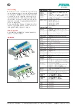
Volt-free
Channels
Switched
Live Outputs
Dimming
Channels
Comms
Bus (MLS)
Mains
Input
Detectors
Switches
1-3
Additional
Switches
Aux 1
High Density
Additional
Switches
GB


