Chapter 3 - Plan and Install MLPLC
Achieving the topology for ML200R
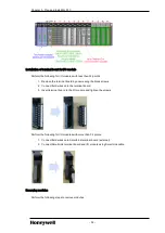
ML200R has a redundant system for CPU, power supply, and communication modules.
Install two identical sets of main bases consisting of same power supply, CPU, and communication
modules and connect two CPU modules with synchronization cable.
One of the two CPU modules is a master system in control of the main operation and another is a
standby system for backup control, if the master fails during operation.
After recovering from a fault, ex-Master CPU can be operated as a standby system and you can switch
the master with a programming tool or a key switch.
You can select CPU side by a switch on the CPU module (that is, A or B) and duplication of sides gives
an error.
The main base comprises of the following modules.
Item
Model
Main Base
CPU
2MLR-CPUH/T, 2MLR-CPUH/F
Power supply
2MLR-AC12, 2MLR-AC22, 2MLR-AC13,
2MLR-AC23, 2MLR-DC42
Communication
FEnet
Base
2MLR-M02P, 2MLR-M06P
Sync cable
2MLC-F201
Expansion Base
Digital I/O
All types of digital I/O
Analog I/O
All types of analog I/O
Communication
Module
Pnet/Dnet/Snet I/F module
Power supply redundancy
Redundant power supply can be installed in both main and expansion bases. When one of the power
supplies fails to operate, the system can seamlessly operate with another power supply. Faulty power
supply module can be repaired during operation.
I/O bus redundancy
Expansion bases and cables can be configured as a ring topology so that single communication cable
fault does not stop the system and the operation continues with another cable attached to the system.
In a normal ring configuration, the communication is enabled to the path nearest to the master CPU.
ATTENTION
l
CPU module cannot be installed in the expansion base.
- 37 -


