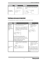
background image

Item

ML200R Comprises of

Main Base

Two main base with identical module

Maximum
Expansion
Base

31 Expansion bases

Max. I/O
modules

Up to 372 (31 X 12) I/O modules (Up to 372 (31 X 12) I/O modules can
be installed in expansion base.)

Maximum
I/O point

16 points module : 5952 points

32 points module : 11904 points

64 points module : 23808 points

Maximum
distance
between
nodes

Fiber Optic : 2km

Twisted pair cable : 100m

l

Total max length

l

Optical multi mode: 62km (when installing 31 expansion
modules)

l

Optical single mode: 465km (when installing 31 expansion
modules)

l

Electrical: 3.1km (when installing 31 expansion modules)

Allocation
of I/O
Address in
Expansion
base

Start address of input and output point is determined by the station
number set in the expansion driver module.

Each slot of the base is allocated 64 points (fixed), irrespective of the
type of module mounted.

Special modules can be mounted in any position. Unlike digital I/O
modules, a special module is not allocated to any I/O address. A special
module is controlled by a dedicated function block and the address is
automatically allocated to the memory.

For instance, the I/O number of 12 slot base is allocated as follows:

Allocation

Only communication module is allowed in the main base. Hence, I/O
addressing is not required. However, same number of points (that is, 768

- 40 -

Chapter 3 - Plan and Install MLPLC

Summary of Contents for ML200 Series

Page 1: ...ML200 Installation and Commissioning Guide EPDOC X366 en 515A November2019 ...

Page 2: ...al Sàrl While this information is presented in good faith and believed to be accurate Honeywell disclaims the implied warranties of merchantability and fitness for a purpose and makes no express warranties except as may be stated in its written agreement with and for its customer In no event is Honeywell liable to anyone for any direct special or consequential damages The information and specifica...

Page 3: ... the power supply 19 Chapter 3 Plan and Install MLPLC 23 3 1 Plan for Engineering Station 23 3 1 1 Platform requirements 23 3 1 2 Prerequisites for Installation 23 3 1 3 Grounding requirements 27 3 1 4 Precautions for installing handling the PLC modules 28 3 2 Mounting Chassis 29 3 3 Achieving the topology 33 3 4 Turn on and start up 42 Chapter 4 Troubleshooting 51 4 1 4 1 Overview 51 4 2 Basic tr...
Page 4: ...ng conventions are used across the document l 2MLI CPUU 2MLI CPUH and 2MLI CPUS are represented as ML200 IEC l 2MLR CPUH T and 2MLR CPUH F are represented as ML200R 1 2 Types of power supply The different types of voltages supported by ML200 IEC and ML200R are as follows l AC 110 V l AC 220 V l DC 24V Power supplies for ML200 IEC The following table lists the types of power modules for ML200 IEC T...

Page 5: ...s for 2MLI CPUS P and ML200R are the same For more details refer to Table 5 Specifications of the power modules for ML200R The following table lists the specifications of the power modules for ML200 IEC Table 3 Specifications of the power modules for ML200 IEC Items 2MLP ACF1 2MLP ACF2 2MLP AC23 2MLP DC42 Input Rated input voltage AC 100V AC 240V AC 200V AC 240V DC 24V Input voltage range AC 85V A...

Page 6: ...ing voltage or current DC 24V 0 5A Minimum switching load DC 5V 1 mA Response time OFF ON ON OFF 10 ms or less 12 ms or less Life Mechanical More than 20 000 000 times Electrical More than 100 000 times at rated switching voltage current RUN signal output Relay output Rating DC24V 0 5A Voltage indicator Output voltage normal LED ON Cable specification 0 75 2mm2 Compressed terminal RAV 1 25 3 5 RAV...

Page 7: ... 5V circuit Power supplies for ML200R ATTENTION The main reason for using redundant power supply is that it has a component and the CPU checks this component for the status of power failure This component is not available in a non redundant power supply The following table provides the specifications of the power modules for ML200R 1 3 Types of modules The following are the different types of modu...

Page 8: ...s 2MLI A21A AC 220V input 8 points Digital output module 2MLQ RY1A Relay output 8 points 2A independent COM 2MLQ RY2A Relay output 16 points 2A 2MLQ RY2B Relay output 16 points 2A built in varistor 2MLQ TR2A Transistor output 16 points 0 5A sink output 2MLQ TR4A Transistor output 32 points 0 1A sink output 2MLQ TR8A Transistor output 64 points 0 1A sink output 2MLQ TR2B Transistor output 16 points...

Page 9: ...oltage output 8 channels 2MLF DC4S Current output 4 channels isolated 2MLF DC4H Current output 4 channels High speed counter module 2MLF HO2A Pulse input 2 channels open collector 2MLF HD2A Pulse input 2 channels line drive Temperature input module 2MLF RD4A RTD input 4 channels 2MLF RD8A RTD input 8 channles 2MLF RD4S RTD input 4channels Isolated 2MLF TC4S Thermocouple input 4channels Isolated Ev...

Page 10: ...terface DP standard ATTENTION The 2MLL PSRA must be installed only on ML200 IEC CPU bases 1 4 Types of base The ML200 IEC and ML200R comprises of main base and expansion base ML200 IEC Main base The main base of ML200 IEC consists of the power module CPU module I O module special module and the communication module The following table lists the types of bases for ML200 IEC Table 9 Types of bases f...

Page 11: ...special and other communication modules 4 FG terminal The ground terminal connected to the shielded pattern of the PCB board 5 Expansion cable connector Connects the main base CPU base with the expansion base 6 CPU module connector For installation of the CPU module ML200 IEC Expansion base The expansion base consists of the power module I O module special module and the communication module ATTEN...

Page 12: ...Base attached guide hole For attaching the main base to the panel in the control panel 2 Power module connector I O module built in connector 3 Expansion driver module connector I O module built in connector 4 FG terminal The ground terminal connected to the shielded pattern of PCB board 5 Expansion cable connector Connects the main base CPU base with the expansion base ML200R Main base The main b...

Page 13: ...lot The following image illustrates the 2MLR M02P Figure 2 Main base of 2MLR M02P The following image illustrates the 2MLR M06P Figure 3 Main base of 2MLR M06P The following table provides the main base details of 2MLR M02P and 2MLR M06P Table 14 Main base details of 2MLR M02P and 2MLR M06P 11 Chapter 1 Masterlogic components ...

Page 14: ...sion base without dual IO link redundancy l Expansion base with dual IO link redundancy Expansion base without dual IO link redundancy The expansion base of ML200R consists of the power module expansion driver module I O module special module and the communication module Ethernet module is not allowed in the expansion base The following table provides details about the expansion base and expansion...

Page 15: ... FG terminal The ground terminal connected to the shielded pattern of the PCB board Expansion base with dual IO link redundancy The expansion base of ML200R consists of the power module expansion driver module I O module special module and the communication module Ethernet module is not allowed in the expansion base The following table provides details about the expansion base and expansion driver...

Page 16: ...anel in the control panel 2 Power module connector For installation of power supply module 3 Expansion redundancy drive module connector For installation of expansion redundancy driver modules 4 Module built in connector For installation of I O special and other communication modules 5 FG terminal The ground terminal connected to the shielded pattern of the PCB board 1 5 Types of cables Cables for...

Page 17: ...provided for use in accordance with the network type Optical cables The communication between the optical cables is through Multi Mode Fiber MMF 50 65 um LC type cable In ML200R systems cables are used based on the installation site indoor type outdoor type or conduit type ATTENTION 2MLC F201 Multimode Fiber Optic Cable LC connector 2 0m is the synchronization cable part number used for ML200R The...

Page 18: ...s external noise affects the system performance and control the Ethernet cables used in ML200R systems must be twisted pair cables such as UTP FTP STP or FSTP cables The twisted pair cables are known as Cat5 cables The twisted pair cables are categorized on the following two criteria l Shielding It is classified into three types The following table lists the three types of twisted pair based on th...

Page 19: ...f Model Current consumption mA Non redundant CPU Module 2MLI CPUU 960 2MLI CPUH 960 2MLI CPUS 940 2MLI CPUS P 940 Redundant CPU Module 2MLR CPUH T 980 2MLR CPUH F 1310 Expansion Driver Module 2MLR DBST 550 2MLR DBSF 550 2MLR DBSH 550 2MLR DBDT 550 2MLR DBDH 550 2MLR DBDF 550 Digital Input Module DC 24V 2MLI D21A 20 2MLI D22A 30 2MLI D22B 30 2MLI D24A 50 2MLI D24B 50 2MLI D28A 60 2MLI D28B 60 17 CH...

Page 20: ... 130 2MLQ TR4B 130 2MLQ TR8A 230 2MLQ TR8B 230 Digital Output Module Triac 2MLQSS2A 300 2MLFDV4S 200 Analog Input Module 2MLF AV8A 420 2MLF AC8A 420 2MLF AD8A 420 2MLF AD16A 330 2MLF AD4S 610 Analog Output Module 2MLF DV4A 190 2MLF DC4A 190 2MLF DV8A 147 2MLF DC8A 243 2MLF DC4S 200 2MLF DV4S 200 Temperature Input Module 2MLF TC4S 610 2MLF RD4A 490 High Speed Counter Module 2MLF HO2A 270 2MLF HD2A ...

Page 21: ...talled on the same base as the power module The system does not operate normally if the rated output capacity of the power module exceeds the predefined limit Example of current consumption power calculations for ML200 IEC The following table describes which power supply module must be used in coordination with the corresponding modules for ML200 IEC Type Model Quantity Voltage 5V CPU module 2MLI ...

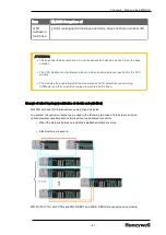
Page 22: ...A Expansion Base 2MLR E12P 1 0 21 A DI Module 2MLI D24A 2 0 05A DO Module 2MLQ RY2A 6 0 5A AI Module 2MLF AD4S 2 0 61A Profibus DP 2MLL PMEA 2 0 56A Current Consumption Power Consumption 0 65A 0 05A 2 0 5A 6 0 61A 2 0 56A 2 6 09ª 6 09A 5V 30 85 W Sum of current consumption is 6 17A Hence use 2MLR AC13 or 2MLR AC23 ATTENTION Maximum power consumption of PLC can be derived from the efficiency of pow...

Page 23: ...hout DC 24V is used it is not applicable 2 Sum of DC 5V circuit current consumption The DC 5V output circuit current of the power supply module is the sum of current consumption of each module W 5V I5V X 5 W 3 DC 24V average current consumption current consumption of simultaneous ON point DC 24V output circuit average current of power module is the sum of current consumption of each module W 24V I...

Page 24: ...ion of the PLC system W WPW W5V W24V Wout Win Ws W Calculate the amount of radiation according to this total current consumption W and review the temperature rising in the control panel Use the following formula for the calculation of the temperature rise in the control panel T W UA C Where W power consumption of the entire PLC system the calculated value A surface area of control panel m2 U If eq...

Page 25: ...ng System Compatible with Windows XP Vista 7 Only the RS 232C or USB port must be used while configuring the PLC for the first time PLC without any data After the IP for FEnet module is configured the Ethernet option can be used for connecting SoftMaster with PLC provided the system has Ethernet port ATTENTION Refer to the ML200 CPU and SoftMaster User s Guide for further information about install...

Page 26: ...n conditions l While drilling holes fixing screws or wiring ensure that no wire or any other metallic part enters PLC l Do not install PLC on a panel that has a high voltage device l Maintain a distance of at least 50mm from the wiring duct or surrounding modules l Ensure the grounding at a place where surrounding noise is minimal Heat protection design of control panel l In case the PLC is instal...

Page 27: ...ear a Contactor Breaker it is recommended to use a Contactor Breaker Large Size in a different panel 5 If necessary install wiring duct for routing the cables Consider the following points while installing a wiring duct l When installing the wiring duct on the upper part of the PLC ensure that its distance is more than 50mm to enable adequate ventilation Maintain sufficient distance from the upper...

Page 28: ...elay and electronic contact with a spacing secured as indicated in the following figure 9 Installing a base on top of another leads to a rise in temperature of the cabinet l Install a fan for air circulation or keep maximum distance between the bases 26 Chapter 3 Plan and Install MLPLC ...
Page 29: ...d the module does not exceed 55 C 3 1 3 Grounding requirements Grounding for cabinet mounting 1 Take sufficient measures against noise in PLC making it possible to be used without grounding 2 Use dedicated grounding for the wires as far as possible 3 If the grounding is functional use class 3 grounding grounding resistance must be 100Ω or less 4 If it is not possible to use dedicated grounding use...

Page 30: ...dule casing remove them immediately Precautions for installing handling I O module Note the following points while handling or installing the I O module 1 Recheck I O module specifications Check the input voltage for input modules For output modules check if the voltage applied exceeds the maximum Open Close capacity Over voltage may lead to failure damage or sparking 2 Cable selection Select the ...

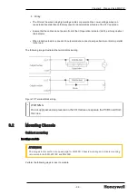
Page 31: ...l When inductive load is connected to output module connect a surge absorber or diode parallel to the load The following image illustrates the terminal block wiring Figure 10 Terminal block wiring WARNING Do not apply excessive pressure on the I O module or separate the PCB board from the case 3 2 Mounting Chassis Cabinet mounting Inserting a module ATTENTION The images in this section are an exam...

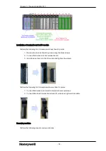
Page 32: ...tion on the lower part of the module into the module fixing hole of the PLC base as shown in the figure 4 Slide the upper part of module to fix into the base Use the screws in the upper part of the module to hold the module firmly to the base TIP To check if the module is properly installed in the base slowly pull the upper part of the module 30 Chapter 3 Plan and Install MLPLC ...
Page 33: ...he fixed projection of the module into the module fixing hole and then press it The module may break if the module is forced onto the base in an incorrect position The following image illustrates the modules mounted in the CPU base The following image illustrates the modules mounted in the IO base 31 ...

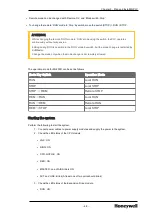
Page 34: ...res onto the terminal board 3 Insert terminal board to the I O module and tighten the screws Perform the following for I O modules with more than 32 points 1 Connect field wires onto SmartLink terminal board external 2 Connect SmartLink terminal board and I O module using SmartLink cable Removing modules Perform the following steps to remove modules 32 Chapter 3 Plan and Install MLPLC ...

Page 35: ... the fixed projection of the module from the fixing hole Figure 12 Removing modules CAUTION While removing the module press the hook and remove the module from the base Then remove the fixed projection of the module from the module fixing hole If module is detached forcefully the hook or the fixed projection of the module may break 3 3 Achieving the topology Achieving the topology for ML200 IEC ML...

Page 36: ...the expansion base has a switch to set the base number l The module starts operating once the the module type and I O parameter are set using SoftMaster and the correct module type is mounted on the base l 2MLI CPUS P does not support expansion base 34 Chapter 3 Plan and Install MLPLC ...

Page 37: ...main base and the expansion base to be connected the terminating resistance must be attached to the expansion connector OUT of the last expansion base The terminal resistance is not required to be installed if the system has only the main without expansion bases 1 Structure 2 Installation Position Figure 14 Installation point of terminating resistor 35 ...

Page 38: ...ctions M XCHG Module exchange switch To change a module online during CPU operation hot swapping l ON right Before changing the module set the switch to ON position l OFF left After the module is changed set the switch back to OFF position RUN STOP mode Switch Sets the operation mode of CPU module l STOP RUN executes the program l RUN STOP stops the program These commands operate irrespective of t...

Page 39: ... modules Item Model Main Base CPU 2MLR CPUH T 2MLR CPUH F Power supply 2MLR AC12 2MLR AC22 2MLR AC13 2MLR AC23 2MLR DC42 Communication FEnet Base 2MLR M02P 2MLR M06P Sync cable 2MLC F201 Expansion Base Digital I O All types of digital I O Analog I O All types of analog I O Communication Module Pnet Dnet Snet I F module Power supply redundancy Redundant power supply can be installed in both main an...

Page 40: ...O racks and CPUs in a Ring Configuration l UTP cable Direct or Cross cable Cross cable is recommended l Fiber Optic cable Tx to Rx Rx to Tx Multi mode FO LC connector type The following image illustrates the ML 200R architecture without dual I O link redundancy Figure 15 ML200R architecture without dual I O link redundancy Architecture with dual I O link redundancy The cable connection for ML200R ...

Page 41: ... the ML200R architecture with dual I O link redundancy Figure 16 ML200R architecture with dual I O link redundancy ATTENTION The images illustrate the architecture of 2MLR CPUH T Electrical The architecture remains the same for 2MLR CPUH F optic fiber The following table describes the topology of ML200R Table 23 Topology of ML200R 39 ...

Page 42: ... installing 31 expansion modules Allocation of I O Address in Expansion base Start address of input and output point is determined by the station number set in the expansion driver module Each slot of the base is allocated 64 points fixed irrespective of the type of module mounted Special modules can be mounted in any position Unlike digital I O modules a special module is not allocated to any I O...

Page 43: ... after the module type and I O parameter are set using SoftMaster and the correct module type is mounted on the base Example of mixed topology combination of electric and optic fiber ML200R with dual I O link redundancy using mixed modules In a system the optical modules can be used in the following two cases This helps to build an optical electrical mixed module network without an additional conv...

Page 44: ... switch Defines CPU classification l CPU module is A if the switch is set to the left l CPU module is B if the switch is set to the right l Two CPU must have different settings you can check it using software l A same setting does not affect operation but may not operate in a normal way Reset D Clear switch Resets CPU when switch is set to the left l Left Center RESET l Left more than 3s Center Ov...

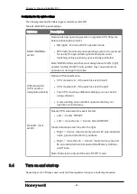
Page 45: ...t and release ATTENTION DO NOT change Boot Normal switch settings l Ensure that the STATION NUMBER is set using the Rotary switch on the Expansion driver module I O device wiring Perform the following steps for I O device wiring l The cable used for I O wiring must be 0 3 2 0mm2 1 Use a separate input and output cable for wiring 2 Separate the I O signal cable by a distance of at least 100mm from ...

Page 46: ...excessive interference noise use an isolation transformer The following figure illustrates the distributions of AC 220V for PLC power supply I O modules and other main circuit equipment 3 While using power module of DC 24V output a Do not connect the module in parallel with the output of several power modules b If DC 24V output capacity of a power module is not sufficient for the PLC I O modules s...

Page 47: ...ning as displayed in the following figure TIP l Separate PLC earth E2 from earth E1 of surge absorber against lightning l In case of an increase in voltage the surge absorber ensures that it does not increase more than the predefined maximum limit l Use a shielded isolation transformer or noise filter in areas where higher noise levels are expected l It is advisable to use twisted cable for input ...

Page 48: ... YELLOW Remote enabled in case REMOTE switch is ON OFF Remote disabled in case REMOTE switch is OFF ERR LED ON RED Error has occurred and CPU cannot operate normally OFF Normal operation PS LED Programmable Status l Red ON l User assigned flag is ON l Operating in the error state by operation proceeding in the error setting l Module is detached or new module is installed in the state where M XCHG ...

Page 49: ...by the operation mode switch l RUN operation by the programming tool with the operation mode switch in REM l Red light STOP mode the module is in operation l STOP operation by the operation mode switch l STOP operation by the programming tool with the operation mode switch in REM WAR LED ON YELLOW Warning OFF Normal ERR LED ON RED Critical Error OFF Normal BAT LED Four digit display of the Operati...

Page 50: ...U module networked with the main CPU l Using a networked SoftMaster HMI and the computer link module l Using the STOP command while a program is operating WARNING Changing the operation mode can energize the field and may cause serious injury to the users Setting operation mode The operation mode for ML200 IECcan is set as follows Operation Mode Switch Remote Switch SoftMaster Command Operation Mo...

Page 51: ...nly when the mode change is not remotely allowed The operation mode for ML200R can be set as follows Mode Key Switch Operation Mode RUN Local RUN STOP Local STOP STOP REM Remote STOP REM RUN Local RUN RUN REM Remote RUN REM STOP Local STOP Starting the system Perform the following to start the system 1 Connect power cables to power supply modules and supply the power to the system 2 Check the LED ...

Page 52: ...ted for the first time an error may appear Rectify the errors and bring back PLC to the Run state Check and ensure that the LED status of the CPU module and Expansion Drive module is as listed previously For more information about troubleshooting see Troubleshooting on page 51 50 Chapter 3 Plan and Install MLPLC ...

Page 53: ...cedures are followed 1 Check the following manually a Operation status Stop and Run b Power On Off status c I O device status d Wiring status I O wiring expansion and communication cable e The status of each displays POWER LED RUN STOP LED I O LED and so on connect to peripherals and check the operation condition and program 2 Check for any abnormality Observe how a fault changes by executing the ...

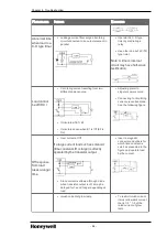
Page 54: ...ff it must be that a neon lamp is still on Leakage current of an external device if operating by a limit switch with neon lamp Input signal cannot be off Leakage current from the capacity between wires of wiring cable l Install the power on an external device as in the following figure Input signal cannot be off Leakage current of an external device if operating by a switch with LED mark l Connect...

Page 55: ...r voltage charged to C is allowed to both ends of diode D When the polarity is The maximum voltage is approximately 2 2 Note While using it as described previously the output element does not have any problem but the performance of diode D in load may be reduced probably causing a trouble l Connect a dozen several hundreds kΩ resistor to a load in parallel Load cannot be off l Leakage current from...

Page 56: ...lar power source l Connecting to circulating current preventive diode See the following figure Off response from load takes a longer time l Over current at Off If a large current load such as solenoid time constant L R is large is directly operated by the transistor output l Since current is allowed through diode when transistor output is off it may be delayed for 1s and longer depending on load l...

Page 57: ...act A S service if it still exists after turning it on again Fault Blink according to LED orders When turning it on 4 Abnormal Click IC RTC Contact A S service if it still exists after turning it on again Fault ERR On When turning it on 6 Abnormal program memory Contact A S service if it still exists after turning it on again Fault ERR On When turning it on 10 Abnormal USB IC Contact A S service i...

Page 58: ... after the program is reloaded Replace a battery in case of abnormal battery After a program is reloaded check the storage condition and if any fault is found replace the CPU module STOP ERR On Reset converting to RUN mode 24 Abnormal I O parameter Restart after I O parameter is reloaded Replace a battery in case of defective battery After I O parameter is reloaded check the storage condition and ...

Page 59: ...Check for detached added slot position by SoftMaster modify the installment and restart according to parameter Reference flag module attachment error flag STOP RUN ERR On P S On When the scan ends 32 Fuse of a module holding a fuse is burnt out during operation Check the position of a slot of which fuse is burnt out by SoftMaster replace a fuse and restart according to parameter Reference flag fus...

Page 60: ...n again 2 Take a measure against noise STOP RUN OnERR On Always 40 The scan time of a program exceeds the scan delay watchdog time designated by parameter during the operation Check the scan delay watchdog time designated by parameter modify parameter or program and restart STOP RUN OnERR On When the program is executed 41 Operation error while executing user program Eliminating an operation error...

Page 61: ...d turn it on again STOP RUN OnERR On When program is executed 101 CPU position error CPU is installed at wrong position Position the CPU correctly STOP S101 Turn it on 102 Duplicated CPU ID error Set the A B side switches of master CPU and standby CPU differently STOP S102 Turn it on 103 Base abnormal error Configure the expansion cable as ring topology and position the detached base correctly For...

Page 62: ... standby CPU as single operation l Disable master CPU STOP mode or power cut l Restart standby CPU through reset switch or by changing the operation mode from STOP to RUN STOP E301 Start standby operation 500 Data memory backup is not possible Turn it on again if battery is normal It is converted to STOP mode in Remote mode STOP ERR On Reset 501 Abnormal clock data Reset the time by SoftMaster if ...

Page 63: ...f any may be found in the materials accompanying the product in the documents or files accompanying such third party materials in a file named third_ party_licenses on the media containing the product or at http www honeywell com ps thirdpartylicenses Documentation feedback You can find the most up to date documents on the Honeywell Process Solutions support website at http www honeywellprocess co...

Page 64: ...ite https www honeywellprocess com en US contact us customer support contacts Pages default aspx Training classes Honeywell holds technical training classes that are taught by process control systems experts For more information about these classes contact your Honeywell representative or see http www automationcollege com 2 ...

Reviews: