Lyric Gateway Installation and Reference Guide
- 9 -
Installing the Gateway (Continued)
Installing the Gateway (Continued)
Installing the Gateway (Continued)
Installing the Gateway (Continued)
AC Power
AC Power
AC Power
AC Power
The Lyric Gateway is powered by a 110VAC, 60 Hz/9 Volt DC, 2.5 Amp Plug-in Power Supply, 300-05763V1
(300-05763V1 –CAN in Canada). Refer to the wiring table below for wire gauge and length.
Use only the
Use only the
Use only the
Use only the 300
300
300
300----05763V1
05763V1
05763V1
05763V1 ((((3
3
3
300
00
00
00----05763V1
05763V1
05763V1
05763V1----CAN
CAN
CAN
CAN in
in
in
in Canada)
Canada)
Canada)
Canada) Power Supply.
Power Supply.
Power Supply.
Power Supply. Do not plug the
Do not plug the
Do not plug the
Do not plug the power
power
power
power
supply
supply
supply
supply into the AC outlet until after all wiring connections have been made.
into the AC outlet until after all wiring connections have been made.
into the AC outlet until after all wiring connections have been made.
into the AC outlet until after all wiring connections have been made.
Wiring Overview
Wiring Overview
Wiring Overview
Wiring Overview
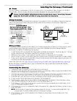
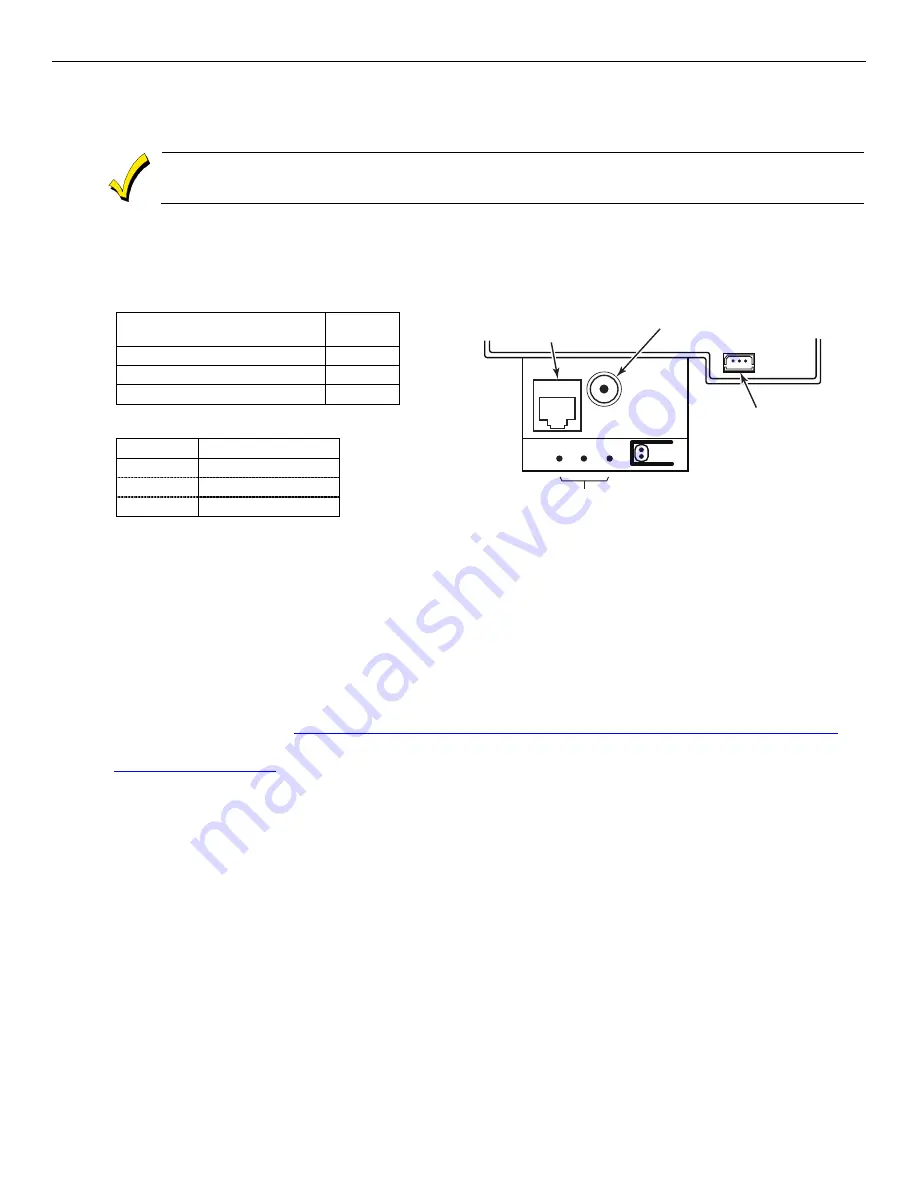
The following summarizes the electrical connections associated with the Lyric Gateway. Follow the steps and
refer to the figure below when making connections. Refer to the Summary of Connections diagram for
additional information.
WIRING TABLE
WIRING TABLE
WIRING TABLE
WIRING TABLE
Maximum Distance Between
Maximum Distance Between
Maximum Distance Between
Maximum Distance Between
Power Supply and Gateway
Power Supply and Gateway
Power Supply and Gateway
Power Supply and Gateway
Wire
Wire
Wire
Wire
Gauge
Gauge
Gauge
Gauge
Up to 8 feet (2.44 m)
# 22
Up to 13 feet (3.96 m)
# 20
Up to 20 feet (6.1 m)
# 18
Recessed
Recessed
Recessed
Recessed
Microswitch Functions
Microswitch Functions
Microswitch Functions
Microswitch Functions
Location
Location
Location
Location
Function
Function
Function
Function
Left
Factory Default
Center
Reboot
Right
WPS
BATTERY
RECEPTACLE
gw-keypad-020-V0
MICROSWITCHES
RJ45
ETHERNET
RECEPTACLE
POWER SUPPLY
RECEPTACLE
Before you begin
Before you begin
Before you begin
Before you begin
The Gateway can be connected to the internet via a hardwire connection or wirelessly via the premise’s Wi-Fi®
router. Programming is done via AlarmNet 360™ using a Smart (Mobile) Device or a laptop computer.
For Wireless Installations the following are required:
•
A smart device with the AlarmNet 360 App loaded or a laptop (referred to as ‘the set up device’). The App
will be used to connect the Gateway panel to the customer’s router onsite.
•
Settings on the customer’s smart device(s) must be set for Wi-Fi operation (Wi-Fi enabled).
•
Access to the customer’s router SSID and WPA or WPA2 password (typically located on the router’s label).
•
If you are not signed up for AlarmNet 360, click on “Dealer Signup” from the login screen to gain access to
the Honeywell web-based programming.
Dealer Sign-Up Direct Link:
https://services.alarmnet.com/AlarmnetDirectP_SignUp/Submission_Agree.aspx
Before starting the installation process, open the AlarmNet 360 App or go to the AlarmNet 360 website
(
www.AlarmNet360.com
)
Connecting the Gateway
Connecting the Gateway
Connecting the Gateway
Connecting the Gateway
1.
Temporarily hang the Gateway from the hook on the wall mount.
2.
Connect the male end of the 110VAC, 60 Hz/9 Volt DC, 2.5 Amp Plug-in Power Supply, 300-05763V1 (300-
05763V1-CAN in Canada) to the receptacle on the Gateway.
3. Install the rear cover on the Gateway OR align the slots on the back of the Gateway with the hooks on the
rear cover/mounting bracket and attach the Gateway to the rear cover/mounting bracket.
4. Once attached, insert the screw to secure the Gateway to the rear cover/mounting bracket.
5. If used, connect the network cable to the Gateway’s RJ45 receptacle.
6. Plug the power supply into a 24-hour, 110VAC unswitched outlet. The Gateway’s Red and Green arming
LEDs will blink alternately for approximately 2 minutes during power up.
7. If the Gateway’s RJ45 ethernet connection is used, at the Gateway touchpad enter Installer Code + 31 to
enter AP Mode and proceed to Step 12.
8. If the connection is via Wi-Fi, proceed to Step 9. When power up is complete the Gateway will be in Access
Point [AP] mode.
NOTE
NOTE
NOTE
NOTE:
:
:
: The AP mode will remain active for approximately 30 minutes. To re-enter AP mode after it has
expired, enter the Master Code and 31 on the Gateway touchpad.
9. If the customer’s router is WPS-capable, at the Gateway touchpad enter Installer Code and 41. If not,
proceed to Step 12.
Summary of Contents for Lyric LCP300-LC
Page 42: ...Lyric Gateway Installation and Reference Guide 42 Notes Notes Notes Notes ...
Page 43: ...Lyric Gateway Installation and Reference Guide 43 Notes Notes Notes Notes ...
Page 44: ...Lyric Gateway Installation and Reference Guide 44 Notes Notes Notes Notes ...
Page 45: ...Lyric Gateway Installation and Reference Guide 45 Notes Notes Notes Notes ...


