


INNCOM e7w THERMOSTAT USER GUIDE
31-00302-01
50
5.
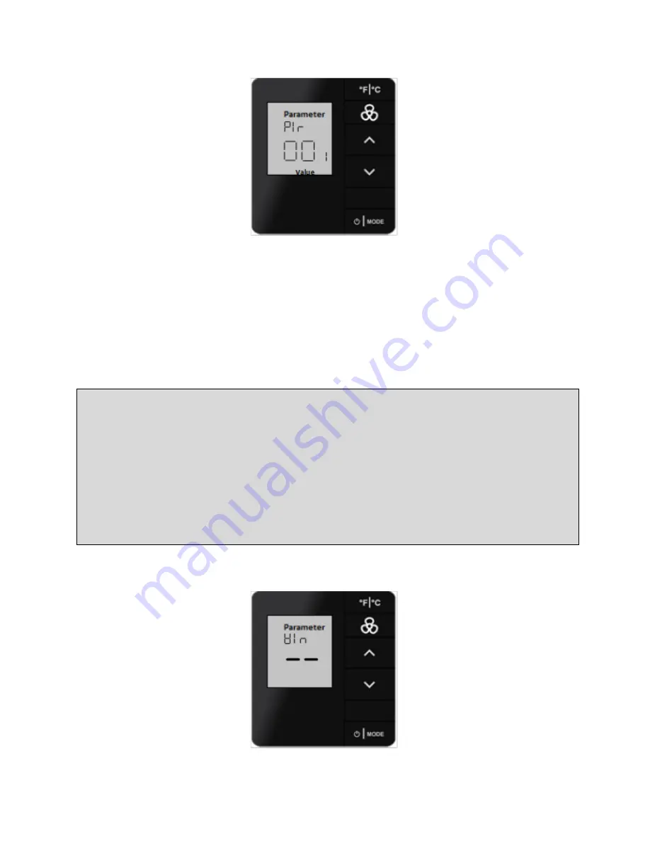
The
PIr
motion test is active for one minute, then automatically timeout.
6.
Press the
F
C
button to return
SERVICE MODE
or press
UP
arrow button to display next
mode.
Or
Press the
F
C
button twice to exit
SERVICE MODE
WIN
–
Verifying Window Position (
Win
)
Use
Win
to verify the monitored window position in the guestroom is reporting correctly.
NOTE
To perform window test, Following two conditions must be satisfied for window test:
•
A device in the room that is monitoring and reporting window position via a 0x0002A1 Win-
dow Open message
•
A device in the room that has its “P5 Window Server” enabled that reports a 0x0002B01
“Window Server Reports window is Open” for the e7w window test to work.
The e7w watches for the0x0002B01 “Window Server Reports Window is Open” message for its win-
dow test.
1.
Enter
SERVICE MODE
2.
Press
UP/DOWN
arrow buttons to select
Win


