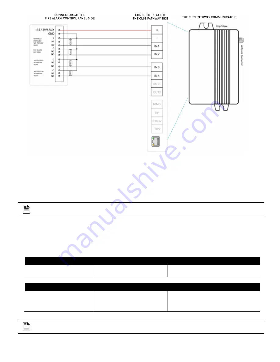
6
Figure 3: Wiring for Dry Contact Relay Monitoring
Powering ON
01. Power ON the communicator and the panel.
02. Ensure that the panel and the communicator are receiving power.
03. Ensure that the Green LED on the communicator is continuously ON indicating successful connections.
NOTE
: Refer to the
Troubleshooting
section if there is an issue and to resolve it.
For Dual-path Communications
01. Connect the LAN port of the communicator to the customer’s network.
02. Observe that the Yellow LED for network connectivity is flashing to indicate a live Ethernet connection.
03. The RJ45 Connector LEDs have the following states:
Yellow LED RJ45 Connector
Indication
Action
The LED is Constantly ON
Connected with good signal
None
Green LED RJ45 Connector
Indication
Action
The LED is Blinking
Cable connection and
communication with the router
are good.
None
NOTE
: Refer to the
Troubleshooting
section if there is an issue and to resolve it.


