background image

Honeywell

18

z

Subnet Mask: Input the corresponding IP subnet mask

z

Default Gateway: Input the corresponding gateway address

z

DNS 1: DNS server IP address

z

DNS2: DNS server standby IP address

z

SNMP: To detect whether it will cause any management attention as device connected on the network

z

SNMP Manager IP:

Input the corresponding

SNMP manager IP address

z

HTTP Port: Input the corresponding port ( Default is 80)

z

HTTPS Port: Input the corresponding port ( Default is 4433)

z

Enable PPPOE: When click Enable PPPOE, the device and HTTP port will mapping to the router automatically

z

Multicast Add

Input the corresponding multicast address

z

Multicast Port

Input the corresponding multicast port (Default is 28080)

z

Device Port: Input the corresponding device port (Default is 5050)

z

Enable PPPOE: Click to enable PPPOE server

PPPOE server: Input the PPPOE server number
Username: Input the username
Password: Input the password
Confirm pwd: Input the password again to confirm it

After all parameters setting completed, click “Save” and the it comes into effect immediately.

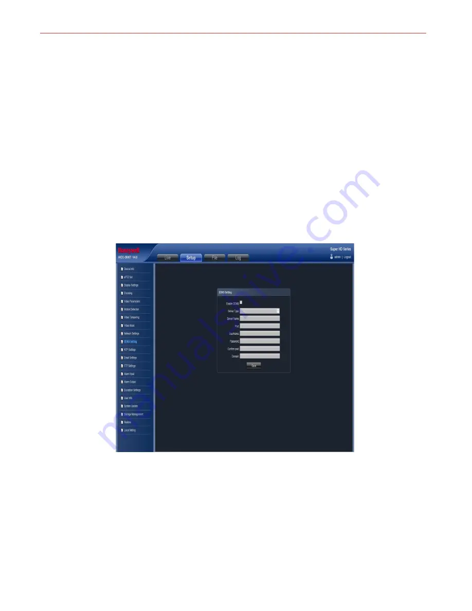
DDNS Setting

DDNS is implemented through a dynamic domain resolution server. It requires a PC with fixed IP address on the Internet, on which

the dynamic domain resolution server runs. IP Camera network setting interface as below:

Figure 3-20

z

Enable DDNS: Click to determine whether to use Dynamic Domain Name Server

z

Server Type: Select DDNS server type (There are Dyndns/ PeanutHull/ NO-IP/ 3322/ DnsDynamic five types selectable)

z

Server Name: Input server name, for example, member.3322.org

z

Port: Input port No.

z

Username: Input user name

z

Password: Input password

z

Confirm pwd: Input the password again to confirm it

z

Domain: Input the standby domain
After all parameters setting completed, click “Save” and the it comes into effect immediately.

Summary of Contents for HISD-2201WE

Page 1: ...Honeywell i Honeywell Network High Speed Dome Operation manual HISD 2201WE IR ...

Page 2: ...specification setting 10 Device Info 10 PTZ setting 10 Display settings 11 Encoding 12 Video Parameters 12 Motion Detection 13 Video Tampering 14 Video Mask 15 Network Settings 16 DDNS Setting 17 NTP Settings 18 Email Settings 18 FTP Settings 19 Alarm Input 19 Alarm Output 20 Exception Settings 21 User Info 22 System Update 23 Storage Management 23 Restore 24 Local Setting 24 File management 25 Lo...

Page 3: ...Rev A Static IP 29 Dynamic IP 30 Internet 30 Frequently asked questions 34 ...

Page 4: ...s where the limits exceed the maximum specified temperature humidity or power supply specifications Contents in this manual may be different from the edition that you are using Should any unsolved problem occur given that the product is used according to this manual please contact our technical support department or your product suppliers This manual content will be updated unscheduled our company...

Page 5: ......

Page 6: ... receiving the products The packing list is as below Part Quantity HISD 2201WE IR 1 Wall mounting bracket 1 Rubber blanket 1 Screws bag 1 Operation manual 1 Certificate of approval 1 CD 1 Contact your local retailer if anything is missing in your package HISD 2201WE HISD 2201WE IR ...

Page 7: ...ocess z Alarm linkage output TF card video recording snapshot FTP upload Email inform Link preset CMS inform z ONVIF Profile S protocol compatible with Honeywell HUS and NVR z 360 horizonal continuous rotation vertical 0 90 256 presets No monitoring blind area z Up to 100m IR distance HISD 2201WE IR z Efficient IR array low power consumption MTTF up to 30 000 hours z 2CH alarm input 1CH alarm outp...

Page 8: ...emperature resource and environment improper place for ventilation avoid install on shaky place Recommend operating environment HISD 2201WE Indoor 10 50 Outdoor 30 C 60 C HISD 2201WE IR Indoor 30 60 Hardware installation steps Please make sure LAN and WAN are working order before installation of the IP camera After checked all the network system in good condition keep your hands clean and dry foll...

Page 9: ...201WE Figure 2 3 HISD 2201WE Figure 2 4 HICC 2201TVI Figure 2 5 HISD 2201WE Remove the screws Press the buckles beside the camera and put out the main part about zoom Insert Micro SD card following the direction shown in Figure 2 5 ...

Page 10: ...t the power supply Please read the Note carefully any question you should contrast us without hesitation Note When open the box please check all of parts carefully confirm the parts in the box as same as packing list Please read the user manual carefully before the installation Remove the screws with 7 wrench Remove the screws here TF card slot Insert Micro SD card following the direction shown in...

Page 11: ...onnect IP camera with concentrator or switchboard of the LAN WAN connection Use one network line to connect IP camera with Router or XDSL Modem Cable Modem as shown bellow Connect the power supply After connect the power source the network camera will start operation automatically Connection instruction Analog video output Power supply input RJ45 Alarm output 485 A B port Audio input Audio output ...

Page 12: ...s to set the IE browser Download and Install ActiveX You need to install ActiveX Control when you visit IP camera for the first time through IE browser ActiveX installing method Download installation Input the IP address of IP camera default address http 192 168 1 188 in Internet Explorer to enter into login page users can refer to the NETWORK SETTINGS under SETUP menu to set the network Notice th...

Page 13: ...nstallation As figure 3 2 Figure 3 2 Select the ActiveX installation and storage file the default installation and storage file is c Program Files webactivex and click Next to enter next dialog As figure 3 3 Figure 3 3 Click Install to enter into the next dialog As figure 3 4 ...

Page 14: ...e 3 5 Login Reopen Internet Explorer after ActiveX installation completes input IP address http 192 168 1 188 of the IP camera to turn to login page enter username default setting is admin and password default setting is blank click login to enter into main interface see Figure 3 6 Figure 3 6 ...

Page 15: ...ON OFF selectable When select ON the icon turn blue as and device do video recording and saved in the appointed files as I8 format z Alarm Info Warns light flashing when camera device inform alarm Support kinds of alarms record and setup or remove the alarm setting clear the alarm information z Zoom in Use the mouse to do local zoom for the video display area by scrolling the mouse wheel z PTZ con...

Page 16: ... number on the tracking drop down list then click after a series PTZ operation click to complete and storage the tracking Clear tracking path Select a tracking number on the tracking drop down list click to clear it Call tracking path Select a tracking number on the tracking drop down list click to call it Cyclotron arrow Restore the default parameters As figure 3 10 Figure 3 8 Figure 3 9 Figure 3...

Page 17: ...ype z Serial No Display the product serial No z Master Version Display the software version date z Hardware Version Display the hardware version number z Format Switch to select the PAL and NTSC image scanning system z Device Time Set and display the device current time After all parameters setting completed click Save and then it comes into effect immediately PTZ setting IP Camera ePTZ Set interf...

Page 18: ...d Connect analog high speed dome at the IP camera AB port set the protocol and baud rate and control the high speed dome through IPC preview interface After all parameters setting completed click Save and the it comes into effect immediately Display settings IP Camera Display settings interface as figure 3 13 Figure 3 13 z Name Modify the appointed channel name ...

Page 19: ...terface as figure 3 14 Figure 3 14 z Compress type Main Stream Normal Sub Stream Main Stream Event selectable z Stream Including complex stream video stream two types z Resolution According to the front camera supported how the camera resolution type supported the corresponding resolution will selectable z Bitrate Type Constant Variable selectable z Bitrate Set different bitrate for different chan...

Page 20: ...Normal z Mirror Close Horizonal Mirror Vertical Mirror 180 Rotation four options default is Close z WDR Close Low Medium High four options default is Close z 3DNR Close Low Medium Higher High five levels default is Close z Sharpness 0 255 selectable default is 128 z Gain Low Lower Medium Higher High selectable default is Medium The higher of the Gain the more of the sharpness z Sharpness Auto 1 30...

Page 21: ...ox when alarm triggered z Snap Snapshot and install the picture in the HDD when alarm triggered z Alarm Output There is a warner connect the alarm output port alarm triggered the embedded relay switch to make alarm output z Enable PTZ Alarm input to link the PTZ motion z Preset Alarm input to link the preset z Snap Interval Set the snapshot interval time z Snap Count Set the snapshot count in ever...

Page 22: ...t and install the picture in the HDD when alarm triggered z Record Video record and installed in the HDD or send as FTP to keep when alarm triggered z Alarm Output There is a warner connect the alarm output port alarm triggered the embedded relay switch to make alarm output z Enable PTZ Alarm input to link the PTZ motion z Preset Alarm input to link the preset z Snap Interval Set the snapshot inte...

Page 23: ...g completed click Save and the it comes into effect immediately Network Settings IP Camera Network Settings interface as figure 3 19 Figure 3 19 z IPV4 IP protocol version No is 4 z IPV6 IP protocol version No is 6 z Static IP The device IP address is permanent z DHCP Click DHCP when turn on the router s DHCP the camera will get the IP address from router automatically z IP address Input the corre...

Page 24: ...enable PPPOE server PPPOE server Input the PPPOE server number Username Input the username Password Input the password Confirm pwd Input the password again to confirm it After all parameters setting completed click Save and the it comes into effect immediately DDNS Setting DDNS is implemented through a dynamic domain resolution server It requires a PC with fixed IP address on the Internet on which...

Page 25: ...erver IP address z NTP Port Only TCP transmission supported default is 123 z Adjust time interval Input the interval time z Select Time Zone Different area time format selectable z GMT Adjust the time more exact After all parameters setting completed click Save and the it comes into effect immediately Email Settings IP Camera Email Settings interface as figure 3 22 ...

Page 26: ... Input the address of the inbox After all parameters setting completed click Save and the it comes into effect immediately FTP Settings IP Camera FTP Settings interface as figure 3 23 Figure 3 23 z Enable Click to determine whether to use FTP z Server Address Input the upload server address z Port Input the server port default is 21 z Username Input the upload username z Password Input the upload ...

Page 27: ...triggered z Record Click it will do video record automatically when alarm triggered z Alarm Output There is a warner connect the alarm output port alarm triggered the embedded relay switch to make alarm output z Snap count Set the snapshot count in every second z Snap Interval Set the snapshot interval time z Enable PTZ Click Enable PTZ it will linkage PTZ operation when alarm input z Preset set t...

Page 28: ... comes into effect immediately Exception Settings IP Camera Exception Settings interface as figure 3 26 Figure 3 26 z Exception Type Disk full disk fault network broken IP address conflict Illegal access video signal exception types selectable z Record Click Record it will do video record as any exception type triggered the alarm output z Alarm Click Alarm Output it will Linkage other alarm device...

Page 29: ...default default indicates general users booth and login with permissions authorized to default users default Figure 3 27 z Modify Modify the new user password user type IP combine MAC combine z Del Delete the new user z Rights Permission permission assignment for new user z Add User Add a new user After all parameters setting completed click Save and the it comes into effect immediately ...

Page 30: ... kit then click Update Non technician should not try to operate system upgrade do not turn off the power during upgrade process Storage Management IP Camera Storage Management setting interface as below you can check current HDD capacity spare capacity status and do HDD formatting Note Turn off the power supply when insert or take out the TF card ...

Page 31: ...5 Figure 3 29 Restore IP Camera Restore setting interface as figure 3 30 Figure 3 30 z Restore Restore to factory setting z Reboot Reboot the devices Local Setting IP Camera Local Setting interface as figure 3 31 ...

Page 32: ...ath z Preview Capture Select the preview video record file storage path z Record File Type AVI I8 format selectable z Color Realtime Smooth way two types selectable After all parameters setting completed click Save and the it comes into effect immediately File management IP Camera File management setting interface as figure 3 32 Figure 3 32 ...

Page 33: ...video image file z Frame Click button to play the backup video image file by frame z Capture Click button to snap the backup video image during display z Voice Click button to select turn on off the voice during backup video image display Log search IP Camera Log setting interface as figure 3 33 Figure 3 33 z Main Type There are All Alarm Exception Settings Operation Additional Information four ty...

Page 34: ...DDLE HIGH OFF Electronic Image Stabilizer ON OFF Operation Pan travel 360 endless Tilt travel 0 90 Manual Speed 0 1 300 s 0 1 150 s Presets 256 Preset Accuracy 0 1 Preset Speed 300 s 180 s Swing 8 Continuous Support Cruise 8 Pattern 4 Privacy zones 8 Proportional Pan tilt AUTO Home Function Preset Swing Cruise Pattern Auto Flip Mechanical Resume after Power loss Support IR irradiation distance 100...

Page 35: ...ry CE FCC type examination report Note Honeywell reserves the right without notification to make changes in product design and or specifications Network Interface of IP Camera The default network ports of IP camera are Default Network Parameters Default network parameters Cabled Network IP Address 192 168 1 188 Data Port 5050 Subnet mask 255 255 255 0 Web port 80 Gateway 192 168 1 1 DHCP OFF TCP 8...

Page 36: ... address IP Camera DDNS analytical process Visit IP camera under different network environments Users visit the IP camera through LAN WAN The following directions will tell you how to operate the IP camera through LAN WAN LAN There two ways to connect IP camera Static IP Dynamic IP Static IP Static IP means the webmaster distribute a LAN inner IP address to the IP camera Keep your PC IP address sa...

Page 37: ...meters click Save then the device restart Input the device IP address at the IE browser to visit the camera Dynamic IP Dynamic IP means that IP camera obtains IP address from DHCP server See below picture for the network topology Please refer to below picture for the network settings Log in IP camera via IE browser Then turn to Network Setting interface click DHCP After setting all the parameters ...

Page 38: ...allation 1 Switch to the page network settings fill in the device IP address requested from network service provider in to Basic Parameters such as 218 84 31 168 2 enter correct subnet mask Such as 255 255 255 0 3 enter correct gateway address Such as 218 84 31 131 After setup completes click Save and restart the device then connect it to public network so that all Internet users can visit the IP ...

Page 39: ...nd password 2 Click DDNS It is selectable when server provider is blank 3 Select DDNS server provider such as no ip 4 Input the DDNS login username 5 Input the DDNS registered password 6 Input the domain name applied on the DDNS server such as video no ip net 7 Input the DDNS address such as dynupdate no ip com 8 Input the DDNS port default is 80 Suggested users keep it After all parameters settin...

Page 40: ... 100 port e g 85 status valid and other information click save see below picture 4 After save successfully below screen appears 5 If DDNS is successfully set in Network Settings of IP camera direct visit to the IP camera can be realized via entering http test mvddns net 85 into IE browser ...

Page 41: ...omatically After enter into the back up programmer upgrade system After upgrade completes the IP camera will work normally The back up programmer offers only upgrade and parameter setup functions audio and video functions are not available 3 No video image displayed in IE browser Possible reason ActiveX not installed Solution ActiveX must be installed when visiting IP camera for the first time via...

Page 42: ...ay properly for the difference between Graphics Cards the images appears to be green or other colors then you should run the programme Config exe or run C windows system32 Config exe to set the following parameters of display buffer auto detection used display card memory or system memory then reopen IE and connect IP camera 7 There is no sound while monitoring Possible Reason 1 No audio input con...

Page 43: ...848 39106012 13 Email security ea honeywell com https www asia security honeywell com Thailand office 252 121 25th Floor Muang Thai Phatra Office Tower II Ratchadapisek Road Huay Khwang Bangkok Thailand 10320 Tel 66 2 693 3099 Email security ea honeywell com https www asia security honeywell com Indonesia Office Sastra Graha 5th Floor Suite 509 Jalan Raya Pejuangan No 21 Jakarta Indonesia 11530 Te...

Reviews: