Honeywell HEN04102 User Manual Download Page 103

Configuring Event Settings  |  103

800-21090V2 - A - 03/2016

Note

The best way to configure motion detection is to experiment with the sensitivity 
and threshold settings while someone is walking in front of the camera.

6.

By default, motion detection 

Region1

 covers the whole screen. 

To disable motion detection in part of the image, drag the mouse over the area of the 
image that you want to exclude. The areas 

not

 covered by red boxes are 

not

 sensitive 

to motion.

To change the threshold level in part of the image, select a different motion detection 
region (

Region2

Region3

, or 

Region4

), set the 

Threshold

 level for that region, and 

then drag the mouse to define the region.

7.

Right-click to return to the 

SETTING

 menu.

8.

Click 

Apply

 to save your settings.

9.

If you want to save your settings and exit the 

SETTING

 menu, click 

OK

.

To set up motion detection periods

1.

On the 

Motion Detect

 tab, next to 

Period

, click 

Set

. The 

Set

 window opens.

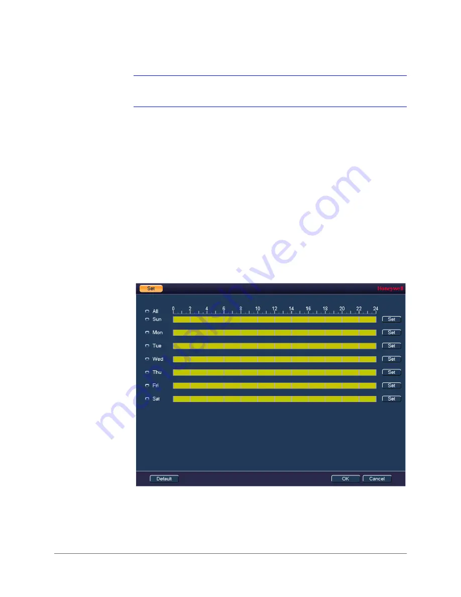
Figure 8-3

Motion Detection Schedule Configuration Window

2.

By default, when motion detection is enabled, it is active all the time. To modify the periods 
when motion detection for the selected channel is active, on each day’s timeline, click the 
half-hour blocks when you want motion detection to be 

disabled

.

3.

Alternatively, for the day of the week that you want to configure, click 

Set

. The 

Period


window opens.

Summary of Contents for HEN04102

Page 1: ...Document 800 21090V2 Rev A 03 2016 User Guide Performance Series Full PoE Network Video Recorder HEN04112 HEN08112 HEN16122 HEN04122 HEN08122 HEN16142 HEN04102 HEN08142 HEN16162 HEN08102 HEN16102 ...

Page 2: ......

Page 3: ...User Guide ...

Page 4: ... in the Camera Configuration chapter V2 Rev A 03 2016 Amended the part numbers Amended the product description Added the Smart Search section in the Playing Back Video section Amended some Specifications Added the appendix about MAXPRO Cloud Added the list of symbols in the Cautions Safety Regulatory chapter ...

Page 5: ...d be performed only by qualified and experienced technicians to conform to all local codes and to maintain your warranty Regulatory Statements FCC Compliance Statement Information to the User This equipment has been tested and found to comply with the limits for a Class B digital device pursuant to part 15 of the FCC Rules These limits are designed to provide reasonable protection against harmful ...

Page 6: ... operate the equipment This Class B digital apparatus complies with Canadian ICES 003 Cet appareil numérique de la Classe B est conforme à la norme NMB 003 du Canada Manufacturer s Declaration of Conformance North America The equipment supplied with this guide conforms to UL 60950 1 and CSA C22 2 No 60950 1 Europe The manufacturer declares that the equipment supplied is compliant with the essentia...

Page 7: ...uding amplifiers 5 WATER AND MOISTURE Do not use this unit near water or in an unprotected outdoor installation or any area classified as a wet location 6 MOUNTING SYSTEM Use only with a mounting system recommended by the manufacturer or sold with the product 7 ATTACHMENTS Do not use attachments not recommended by the product manufacturer as they may result in the risk of fire electric shock or in...

Page 8: ...r recovery and recycling By separating this product from other household type waste the volume of waste sent to incinerators or landfills will be reduced and thus natural resources will be conserved The UL compliance logo This logo indicates that the product has been tested and is listed by the Underwriters Laboratories The FCC compliance logo This logo indicates that the product conforms to Feder...

Page 9: ... conforms with the Australian RCM guidelines The TVU Lab symbol This symbol indicates that the product has been safety tested by the TUV Lab The Direct Current symbol This Direct Current symbol indicates that the product operates direct current This symbol indicates that the product is to be used indoors The CE Compliance logo This logo indicates that the product conforms to the relevant guideline...

Page 10: ...Guide This symbol is used to direct attention to important information This symbol warns that the corresponding action could result in an electric shock This symbol indicates On Standby functionality of the corresponding control button switch Table 1 1 List of Symbols Symbol Explanation ...

Page 11: ... NVR 38 Setting Up the NVR with the Startup Wizard 39 Using the Startup Wizard 39 Setting Up Bi Directional Communication Connection 44 Audio Output Device to a PC 44 Connect 44 Configuring to Hear Audio From the NVR 44 PC to an Audio Input Device 44 Connect 44 Configuring to Hear Audio from the PC 45 3 Viewing Live Video 47 About Live View 47 Camera Status 48 Camera Toolbar 48 Live View Toolbar 5...

Page 12: ...ection Settings 88 Configuring Advanced Network Settings 90 Configuring PPPoE Settings 90 Configuring DDNS Settings 91 Configuring IP Filter Settings 92 Configuring Email Settings 93 Configuring FTP Settings 94 Configuring UPnP Settings 95 Configuring SNMP Settings 96 Configuring Multicast Settings 97 Configuring Automatic Registration Settings 98 Configuring Alarm Center Settings 98 Configuring S...

Page 13: ...uring RS232 Settings 132 Configuring Pan Tilt Zoom Settings 133 Configuring Account Settings 133 Configuring Automatic Maintenance Settings 137 Exporting and Importing System Configurations 139 Restoring Default Settings 141 Upgrading the NVR 142 11 Viewing Information 145 Viewing System Information 145 Viewing HDD Information 145 Viewing Recording Information 147 Viewing Data Stream Information 1...

Page 14: ...puts 161 Before Connecting Alarm Inputs and Outputs 161 Alarm Input and Output Rear Panel Connections 161 Guidelines for Connecting Local Alarm Input Ports 162 Guidelines for Connecting Alarm Output Ports 162 Appendix B Installing Hard Drives 163 Hard Disk Drive Recommendations 163 Installing Hard Drives 164 Installing a HDD 164 Installing an additional HDD 166 List of Compatible SATA HDDs 167 Lis...

Page 15: ...ring to Hear Audio from the NVR 44 Figure 2 11 Configuring to Hear Audio from the PC 45 Figure 3 1 Live View 48 Figure 3 2 Live View Camera Toolbar 48 Figure 3 3 Live View Toolbar 50 Figure 3 4 Shortcut Menu 51 Figure 3 5 PTZ Control Panel 52 Figure 3 6 Expanded PTZ Control Panel 53 Figure 3 7 System Setting PTZ 54 Figure 4 1 Storage Recording Settings 62 Figure 4 2 Storage Schedule Settings 63 Fi...

Page 16: ...on Detection Region Configuration Window 102 Figure 8 3 Motion Detection Schedule Configuration Window 103 Figure 8 4 Motion Detection Period Configuration Window 104 Figure 8 5 Motion Detection Configuration Tab 105 Figure 8 6 Video Loss Configuration Tab 106 Figure 8 7 Video Masking Configuration Tab 107 Figure 8 8 HDD Abnormality Configuration Tab 108 Figure 8 9 Network Abnormality Configuratio...

Page 17: ... 147 Figure 11 4 BPS Information Window 148 Figure 11 5 Version Information Window 149 Figure 11 6 Event Information Window 150 Figure 11 7 Viewing Online Users 151 Figure 11 8 Blocking Online Users 152 Figure 11 9 Viewing Network Load 153 Figure 11 10 Testing the Network 154 Figure 11 11 Viewing Log Information 155 Figure 11 12 Find USB Device Window 155 Figure B 1 Removing the NVR Cover 164 Figu...

Page 18: ...www honeywell com security 18 Performance Series Full PoE Network Video Recorder User Guide ...

Page 19: ...ble 1 1 IP Cameras Features 26 Table 1 2 NVR Front Panel Components 27 Table 1 3 NVR Back Panel Components 30 Table 3 1 Live View Camera Toolbar 48 Table 3 2 Live View Toolbar 50 Table 3 3 PTZ Controls 52 Table 3 4 Expanded PTZ Control Panel 53 Table D 1 Specifications 173 ...

Page 20: ...www honeywell com security 20 Performance Series Full PoE Network Video Recorder User Guide ...

Page 21: ...bes how to manually record a video clip and how to set up automatic recording Chapter 5 Playing Back Video describes how to search for and play back recorded video and snapshots and how to save recorded files to an external storage device Chapter 6 Configuring Camera Settings describes how to configure camera image settings encoder settings snapshot settings privacy mask settings camera name setti...

Page 22: ... how to switch the NVR for MAXPRO Cloud mode Appendix D Specifications lists the NVRs specifications Appendix E Index lists commonly searched for terms Related Documents This document is a necessary prerequisite for understanding the Performance Series Full PoE Network Video Recorder For more information please refer to the following documents Document title Part number Description Embedded NVR Qu...

Page 23: ...ayed on the screen Syntax The message Unauthorized displays object entered Swiss721 BT Bold Words or characters that you must type The word enter is used if you must type text and then press the Enter or Return key Enter the password Menu titles and other items you select Double click Open from the File menu Buttons you click to perform actions Click Exit to close the program Italic Placeholders w...

Page 24: ...www honeywell com security 24 Performance Series Full PoE Network Video Recorder User Guide ...

Page 25: ...rder It supports Local preview Multiple window display Local recorded file storage Remote control and mouse shortcut menu operation Remote management Control The Performance Series Full PoE Network Video Recorder also features multiple storage options Central storage 3rd party storage such as network storage Front end storage The NVR s HDD storage Client end storage Storage on the client s compute...

Page 26: ...ived from various connected peripheral devices Network Monitor The NVR supports the transmission of audio video data that is compressed by an IP camera which is then decoded for display The delay time is less than 500 ms sufficient network bandwidth support is required Supports a maximum of 10 connections Compatible to broadcast audio video with the following transmission protocols HTTP TCP UDP MU...

Page 27: ... and PAL Supports viewing real time system resources information and running statistics display Supports log file Supports local GUI output and shortcut menu operation with a computer mouse Supports IR control using shortcut menu operation with a computer mouse Supports IP camera remote video preview and control Table 1 1 IP Cameras Features Category Features Table 1 2 NVR Front Panel Components C...

Page 28: ...ay Click to adjust the playback speed Various slow playback speeds are available Fast Play Click to adjust the playback speed Various fast playback speeds are available Reverse Pause II Normal playback Click to reverse playback Reverse playback Click to pause playback Play Pause II Reverse playback or pause mode Click to return to normal playback mode Normal playback Click to pause playback Pause ...

Page 29: ...ect to a USB 2 0 storage device USB 2 0 mouse or CD DVD burner HDD Abnormal Indication Light HDD Lights BLUE to indicate an HDD error or when the HDD capacity is below the specified threshold Network Abnormal Indication Light Net Lights BLUE to indicate that a network error has occurred or that there is no network connection Table 1 2 NVR Front Panel Components Component Name Icon Function ...

Page 30: ... to a network cable RS232 RS 422 232 Debug COM For general COM debugging to configure the IP address or to transfer transparent COM data HDMI High Definition Media Interface High definition audio and video signal output port It transmits uncompressed high definition video and multiple channel data to the display device s HDMI port VGA VGA Video Output Port VGA VGA video output port Outputs the ana...

Page 31: ... Normally open alarm output port C Alarm output public end Power Input Port Input 12 V DC Power Button Power On Off button PoE Ports The built in switch supports PoE function It also supports up to 48 V 50 W Power Input Port Switch power port Input 48 V DC VIDEO OUT Video Output Port CVBS output MIC IN Audio Input Port Bi directional communication input port It receives the analog audio signal out...

Page 32: ...n lowercase and uppercase letters click Shift To delete the previous character click the key To insert a space click the key 3 Click Enter to close the on screen keyboard 1 2 3 Button Action 1 Left Click to select a menu option Click in a text field to display the on screen keyboard Click on the on screen keyboard to input letters numbers In multi screen view double click to view the channel full ...

Page 33: ...use Pause resume reverse playback 9 Esc Return to the previous menu or cancel the current operation 10 Rec Manually start stop recording While in the recording interface use the direction buttons to select the recording channel Press and hold the record button to enter the manual recording interface 11 Direction Keys Use the left right keys to switch the currently activated control While in playba...

Page 34: ...www honeywell com security 34 Performance Series Full PoE Network Video Recorder User Guide ...

Page 35: ...Up Bi Directional Communication Connection on page 44 Unpacking the NVR Before you set up the NVR make sure that you have received the following items If any of the items listed above are missing or damaged contact your Honeywell dealer immediately Quick Installation Guide 800 21088 Quick Networking Guide 800 21089 Software CD Power adapter and cable Mouse Remote control CAT5e network cable Termin...

Page 36: ...onnect audio devices if applicable To record audio connect the audio sources to the AUDIO IN connectors To play audio connect an audio output device low impedance headphones speaker or amplifier to the AUDIO OUT connector 200 mV 1 kilohm Step 6 Connect alarm devices if applicable Connect alarm devices to the alarm in out interface If the alarm inputs use external power the device must have the sam...

Page 37: ...Getting Started 37 800 21090V2 A 03 2016 Figure 2 1 Typical NVR Installation ...

Page 38: ...ng Down the NVR Note To shut down the NVR you must be logged in as the admin user or have shutdown privileges assigned to you See Configuring Account Settings on page 133 To prevent damage to the hard drive follow these steps to shut down the NVR 1 In live view mode click anywhere on the screen to display the shortcut menu and then click Main Menu 2 In the Main Menu window click Shutdown 3 In the ...

Page 39: ...ame number language video standard Set the date and time Configure video encoding settings Set up a recording schedule Configure recording settings Configure network settings Note If you want to bypass the wizard and go directly to live view click Cancel To prevent Startup Wizard from opening the next time you start the NVR de select the Startup check box Using the Startup Wizard 1 Click Next Step...

Page 40: ...screen keyboard click the numbers 1 2 3 and 4 on the on screen keyboard 1234 is the default admin password and then click Enter 3 Click OK to go to the GENERAL window Figure 2 4 Startup Wizard GENERAL For more information about configuring settings in the GENERAL window see Configuring General System Settings on page 125 4 Click Next Step to go to the NETWORK window ...

Page 41: ...0V2 A 03 2016 Figure 2 5 Startup Wizard NETWORK Window For more information about configuring settings in the NETWORK window see Configuring TCP IP and Port Settings on page 85 5 Click Next Step to go to the REMOTE DEVICE window ...

Page 42: ...l PoE Network Video Recorder User Guide Figure 2 6 Startup Wizard REMOTE DEVICE Window For more information about configuring settings in the REMOTE DEVICE window see Adding a Remote Device Camera on page 75 6 Click Next Step to go to the SCHEDULE window ...

Page 43: ...ormation about configuring settings in the SCHEDULE window see Configuring the Video Recording Schedule on page 63 or Configuring Storage Settings on page 117 7 Click Finished The message Startup Finished appears Figure 2 8 Startup Wizard Startup Finished Message 8 Click OK to close the wizard ...

Page 44: ...live view monitor Figure 2 9 Enabling Bi Directional Communication Configuring to Hear Audio From the NVR At the NVR end speak through the microphone or the pickup Then you can get the audio from the speaker or earphone from the PC end Figure 2 10 Configuring to Hear Audio from the NVR PC to an Audio Input Device Connect 1 Connect the microphone or the pickup to the audio input port in the PC 2 Co...

Page 45: ...90V2 A 03 2016 Configuring to Hear Audio from the PC At the PC end speak through the microphone or the pickup Then you can get the audio from the speaker or earphone from the NVR Figure 2 11 Configuring to Hear Audio from the PC ...

Page 46: ...www honeywell com security 46 Performance Series Full PoE Network Video Recorder User Guide ...

Page 47: ...ng Live View page 51 Controlling PTZ Cameras page 52 About Live View Live view is the NVR s default mode When you start the NVR live video from the connected cameras is displayed on the screen in a multi channel layout the number of channels displayed depends on whether you are using a 4 channel 8 channel or 16 channel NVR ...

Page 48: ...bar move the mouse pointer to the top of the channel window Figure 3 2 Live View Camera Toolbar Table 3 1 Live View Camera Toolbar System date and time Channel Camera name status channel number Video is being recorded No video signal Motion detected in scene Camera locked Realtime Playback Play back the previous 5 to 60 minutes of recorded video Note The playback time is set to 5 minutes by defaul...

Page 49: ...rding Click again to stop recording The clip is automatically saved to the connected USB storage device Snapshot Save a screen capture to the hard drive or to a connected USB storage device To view the captured image go to Main Menu Operation Search and click the File List button Talk Click to enable or disable bi directional communication with an IP camera that is equipped with both a microphone ...

Page 50: ...u Screen Layout Select screen layout format Tour Control Enables a tour automatically cycles through channel views See Configuring Tour Settings on page 130 Pan Tilt Zoom Open the PTZ control panel See Controlling PTZ Cameras on page 52 Camera Open the Camera setting window See Adding a Remote Device Camera on page 75 Search Open the playback interface See Playing Back Video on page 67 Event Open ...

Page 51: ... multi channel layouts and then click the channel s that you want to display To change the screen display format using the live view toolbar Click a screen layout button on the live view toolbar To change the screen display format using the mouse Rotate the mouse wheel button To move a channel to a different location in the multi channel grid Drag the channel to a new location in the multi channel...

Page 52: ...a network connection using the on screen PTZ control panel Basic PTZ Control Panel Figure 3 5 PTZ Control Panel Table 3 3 PTZ Controls 1 2 4 3 5 Name Function 1 Direction keys Direct camera movement 2 Speed Adjust the camera speed Select a value between 1 and 8 3 Expand Arrow Expand the control panel to display additional options 4 PTZ Trace Direct camera movement by dragging the mouse Zoom in and...

Page 53: ...ick the arrow at the right side of the panel 2 6 5 3 4 7 8 9 1 Name Function 1 Preset Tour Pattern Configure call PTZ functions 2 No Enter number of PTZ function to call 3 Aux Call auxiliary functions 4 Enter Menu Enable up the coax OSD menu configuration for non PTZ camera 5 AutoScan Cause camera to continually pan between two points that you have defined 6 AutoPan Cause camera to continually rot...

Page 54: ... PTZ 3 Configure the following settings 4 Click Apply and then click Save to save your settings and exit Configuring PTZ Functions You can configure presets tours patterns and borders using the PTZ control panel Configuring PTZ Presets You can program preset positions for the PTZ camera For example you can point the camera at a specific location such as a doorway when an alarm event occurs Channel...

Page 55: ...t the camera where you want to set as the preset and then click Set 3 In the Preset box enter a number for the preset and then click Set to save your settings To program additional presets repeat steps 1 through 3 To delete a preset enter the number of the preset that you want to delete in the Preset box and then click Del Preset Note Some protocols do not support the Del Preset function ...

Page 56: ...er of the first preset that you want to add to the tour 3 In the Patrol No box enter a number for the tour 4 Click Add Preset to add the preset to the tour 5 Repeat steps 1 through 5 to add additional presets to the tour To delete a preset enter the number of the preset that you want to delete in the Preset box and then click Del Preset To delete a tour enter the number of the tour that you want t...

Page 57: ...ern in live view mode the PTZ camera automatically moves along the path you have defined To program a pattern 1 On the expanded PTZ control panel click the Pattern button 2 In the Pattern box enter a number for the pattern 3 Click Start and then use the direction arrows to direct the camera 4 When you have finished directing the camera click End ...

Page 58: ...You can define the left and right borders of the PTZ camera s pan movement or scan To program a scan 1 On the expanded PTZ control panel click the AutoScan button 2 Use the direction arrows to set the camera s leftmost limit then click Left 3 Use the direction arrows to set the camera rightmost limit then click Right ...

Page 59: ... expanded PTZ control panel in the No box enter the number of the tour that you want to call and then click the Tour button 2 Click the Tour button again to stop calling the tour To call a pattern 1 On the expanded PTZ control panel in the No box enter the number of the pattern that you want to call and then click the Pattern button 2 Click the Pattern button again to stop calling the pattern Conf...

Page 60: ...www honeywell com security 60 Performance Series Full PoE Network Video Recorder User Guide ...

Page 61: ...such as a USB flash drive to one of the USB ports on the NVR The Find USB device dialog box opens automatically 2 Right click to close the window 3 In live view mode move the mouse pointer to the top of the channel window to display the camera toolbar see Camera Toolbar on page 48 4 On the camera toolbar click the Realtime Backup button to start recording The button changes to green while the NVR ...

Page 62: ...neral Recording Settings to enable automatic or scheduled recording 2 Configure the Video Recording Schedule Configuring the General Recording Settings In the RECORD configuration interface you can do the following Select Auto Schedule recording for the main and extra streams Select Manual recording for the main and extra streams Enable and disable the Snapshot function To configure the general re...

Page 63: ...ule 3 In the PreRecord box enter a time between 0 and 30 seconds The default setting is 4 seconds The pre record time sets how long the NVR records before the scheduled recording start time 4 If the NVR has two HDDs select the Redundancy check box to enable redundant recording on the second HDD This HDD must first be configured on the HDD Manage page see Configuring HDD Management Settings on page...

Page 64: ...K 8 Click Apply to save your settings 9 To copy the recording schedule settings to additional channels click Copy select the channels to which you want to copy the settings and then click OK Configuring the Snapshot Recording Schedule Follow these steps to configure the snapshot recording function When enabled the NVR can take snapshots when a motion detection video loss video tampering or an alar...

Page 65: ...y and then click OK to copy the settings and exit 6 Click Apply to save your settings 7 If you want to save your settings and exit the SETTING menu click OK 8 To copy the record schedule settings to additional channels click Copy select the channels to which you want to copy the settings and then click OK To configure snapshot recording settings 1 In the SETTING field in the Main Menu go to REMOTE...

Page 66: ...pshots then the system activates an activation snapshot when an alarm occurs If there is no alarm then the NVR takes snapshots according to the schedule setup Mode Select Timing to take snapshots according to a schedule Select Trigger to take snapshots when a motion detection video loss video tampering or alarm event occurs Image Size The size is automatically selected based on the resolution of t...

Page 67: ...s Playing Back Video page 67 Playing Back Snapshots page 70 Backing Up Video and Snapshots page 70 Playing Back Video Searching For and Playing Back Video To search for and play back recorded video by date 1 In the Operation field in the Main Menu go to Search The playback interface opens ...

Page 68: ...to search Normal Alarm Motion or select All Record to search all recording types 5 Click the File List button to display the list of search results 6 From the list of search results double click the recorded video file that you want to play back The video begins playing in the playback window 7 Use the playback controls at the bottom of the screen to control playback Playback modes include slow pl...

Page 69: ... grid is superimposed over the playback window 2 Drag the mouse over the area that you want to search for activity 3 Click the Smart Search button again Playback jumps to all the parts of the video where there is activity in that area 4 To exit Smart Search click the Smart Search button again The message Are you sure to exit smart search now appears Click OK ...

Page 70: ... that you want to play back The snapshot appears in the playback window 8 Playback cycles through all of the snapshot files in the file list at the interval you specified in the Interval box To pause playback click the Pause button in the control panel below the playback window To go to the next snapshot click the Next Frame button To go to the previous snapshot click the Prev Frame button Note Th...

Page 71: ...vely during video playback in the video clip time field enter the desired start time and end time and then click the Save button Figure 5 3 Playback Save Backup Button 5 The Backup window opens displaying the selected video file clip 6 In the Backup window click Backup Save button ...

Page 72: ...B storage device opens Figure 5 5 Backup Browse USB Storage Window 7 Click Start to back up the file s If the backup is successful the message Backup finished appears To back up from outside of the playback interface 1 Insert a USB storage device such as a USB flash drive into one of the USB ports on the NVR The Find USB device dialog box opens ...

Page 73: ...tings 4 Click Add to display the search results in the file list Type Select the file type for which you want to search Note To search for snapshots select PIC as All means all video files excluding snapshots Start Time Enter the start time of the search End Time Enter the end time of the search Record CH Select a specific channel to search or select All to search all channels File Format Select D...

Page 74: ...in the selected time only the first 1024 files in the search period will be displayed Refine the Start Time and End Time to find the desired files for backup 5 Select the check box es of the file s that you want to back up and then click Backup The Browse window of the USB storage device opens 6 Click OK to back up the file s ...

Page 75: ...mote Device Camera page 75 Configuring Camera Settings page 77 Configuring Encoding Settings page 79 Configuring Snapshot Settings page 80 Configuring the Text Overlay page 82 Changing a Camera Name page 83 Adding a Remote Device Camera To add a camera 1 In the SETTING field in the Main Menu go to REMOTE REMOTE ...

Page 76: ...ar in the Found Devices list OR Click Manual Add a Manually configure the following settings b Click Save The newly added camera appears in the Added Device list Found Devices list Channel Select from the drop down menu of options Manufacturer Select Private Panasonic Sony Dynacolor Samsung AXIS Arecont ONVIF PSIA or General IP Address Enter the IP address for the camera TCP Port Enter the TCP por...

Page 77: ...d your IP cameras via a Private Protocol If you have connected via a Private Protocol then the Camera settings will be available If you have connected your IP cameras via other protocols then the Camera settings will not be available To configure a camera s settings 1 In the SETTING field in the Main Menu go to REMOTE Video Audio Camera Figure 6 2 Camera Settings Tab 2 Configure the following sett...

Page 78: ...e increases the sharpness of the video Select from 0 to 100 The recommended range is between 40 and 60 The default value is 50 Note Choosing a higher value can introduce video noise to the image 3D NR Adjusts the monitor window contrast Select from 0 to 100 The default value is 50 3D NR automatically provides a more accurate noise reduction This is based on twice the visual information than conven...

Page 79: ...e Encode tab in the Channel box select the camera that you want to configure Scene Mode This is the white balance You can select different scene modes such as Auto Sunny Night or Customized to achieve the best quality video Scene Modes Auto Auto white balance is on The system automatically adjusts the color temperature to ensure that the video color is correct Sunny The white balance threshold is ...

Page 80: ...or Alarm The secondary stream type is not configurable Compression This setting is not configurable Resolution Set the primary stream to one of the following resolutions 1080P 720P 960H D1 HD1 2CIF or CIF Set the secondary stream to one of the following resolutions D1 CIF or QCIF Note NVRs can detect a connected 1080p or 720p IP camera s resolution as 1080P or 720P automatically Manually set 960H ...

Page 81: ...can be taken at a time Channel Select a channel from the drop down list Mode There are two modes Regular and Trigger If you set Regular mode then you need to set the snapshot frequency If you set Trigger mode then you need to enable snapshots in Event Settings Please see To set up motion detection event actions on page 104 for example Image Size Select a snapshot size Quality Select a snapshot qua...

Page 82: ...y select the Monitor check box and then click Set Drag the time display to the desired position on the screen 4 To set the channel display next to Channel Display select the Monitor check box and then click Set Drag the channel display to the desired position on the screen 5 Click Apply to save your settings 6 To copy the settings to one or more additional cameras follow these steps a Click Copy b...

Page 83: ...n assign each camera a descriptive name specific to your application for example Front Entrance To rename a camera 1 In the SETTING field in the Main Menu go to REMOTE Channel Name Figure 6 6 Camera Name Settings Window 2 Click the text box of the camera that you want to rename and enter the new camera name 3 Click Apply to save your settings ...

Page 84: ...www honeywell com security 84 Performance Series Full PoE Network Video Recorder User Guide ...

Page 85: ... Advanced Network Settings page 90 including Configuring PPPoE Settings on page 90 Configuring DDNS Settings on page 91 Configuring IP Filter Settings on page 92 Configuring UPnP Settings on page 95 Configuring Alarm Center Settings page 98 Configuring Switch Settings on page 99 Configuring TCP IP and Port Settings To configure TCP IP settings 1 In the SETTING field in the Main Menu go to NETWORK ...

Page 86: ...ct DHCP to assign the NVR a static IP address 5 If you selected Static manually enter the IP Address Subnet Mask and Gateway information The IP address subnet mask and gateway are not configurable when Mode is set to DHCP 6 If you want enter Preferred DNS and Alternate DNS addresses 7 To enable faster downloading over the local area network LAN select the LAN Download check box 8 Click Apply to sa...

Page 87: ...e NVR s port settings Ensure that the port settings do not conflict with each other Max Connection Select a value between 0 and 20 The default setting is 20 TCP Port Select a value between 1025 and 65535 The default setting is 37777 UDP Port Select a value between 1025 and 65535 The default setting is 37778 HTTP Port Select a value between 0 and 65535 The default setting is 80 HTTPS Port Select a ...

Page 88: ...pots select the Enable check box To disable automatic connections to Wi Fi hotspots clear the Enable check box To search for Wi Fi hotspots click Refresh To manually connect to a Wi Fi hotspot click Connection To disconnect from a Wi Fi hotspot click Disconnect If a Wi Fi connection is successfully established the Wi Fi hotspot name and connection details are displayed in the WIFI Working Info are...

Page 89: ...r requirements APN Select the wireless connection server that you want to use to access the wireless network AUTH Select the authentication mode that you want to use to access the wireless network PAP or CHAP Dial Number Enter the 3G network dial up number that you received from your Internet service provider User Name Enter a user name for logging on to the 3G network User Password Enter a passwo...

Page 90: ... Menu go to NETWORK PPPOE Figure 7 5 Network PPPoE Settings Window 2 On the PPPOE page select the Enable check box to enable a PPPoE network connection 3 In the Username and Password boxes enter the user name and password provided by your Internet service provider for PPPoE access 4 Click Apply to save your settings 5 If you want to save your settings and exit the SETTING menu click OK 6 Restart t...

Page 91: ... you want to save your settings and exit the SETTING menu click OK 7 Restart the NVR for the new network connection settings to take effect 8 To test the settings on the DDNS page click Test Server IP The address appears automatically unless DDNS Type is set to Private DDNS In that case enter the server IP address of your DDNS service provider Domain Mode If DDNS Type is set to Honeywell DDNS clic...

Page 92: ...the IP Start box and the ending address in the IP End box and then click Add IP Section Both IPv4 and IPv6 address are supported 6 Click Apply to save your settings 7 If you want to save your settings and exit the SETTING menu click OK To block specific sites from accessing the NVR 1 In the SETTING field in the Main Menu go to NETWORK IP Filter 2 On the IP Filter page select the Enable check box t...

Page 93: ...er s email account Port The default TCP IP port used for SMTP is 25 Anonymous Select the check box to hide the sender s address in sent email Username Enter the user name of the sender s email account Password Enter the password of the sender s email account Receiver Enter the email address where you want to send the notification You can enter up to three email addresses Sender Enter the sender s ...

Page 94: ...he Enable check box to enable uploading images to an FTP server 3 Configure the following settings Health Enable select the check box to enable a health check The system sends a test email to check the connection Interval This is the interval the NVR waits before sending out email notifications after an event is detected Enter a time between 0 and 1440 minutes 0 means that there is no interval Ser...

Page 95: ...the remote directory If this is left blank the NVR will automatically create folder names File Length This is the maximum size for image files being uploaded to the FTP server Enter a value between 0 and 65535 MB Image Upload Interval This is the interval for uploading images to the FTP server Enter a time between 0 and 3600 seconds Channel Select a channel to upload images from or select All to s...

Page 96: ...n the Port Info dialog box edit the Service Name Protocol Internal Port and or External Port details and then click OK To delete a mapping relationship from the list click the mapping relationship that you want to delete and then click Delete 4 Click Apply to save your settings 5 If you want to save your settings and exit the SETTING menu click OK Configuring SNMP Settings You can use Simple Netwo...

Page 97: ... the Enable check box to enable multicast 3 In the IP Address box enter a multicast IP address The address must be valid for multicasting and should be in the range 224 0 0 0 to 239 255 255 255 for IPv4 or have the prefix ff00 8 An address in the range 239 252 0 0 to 239 255 255 255 is recommended 4 In the Port box enter a multicast port number or use the default setting 36666 5 Click Apply to sav...

Page 98: ...the proxy where the proxy has a switch function In the network service the device supports the server address of the IPv4 To configure the automatic registration settings 1 Configure the proxy server address port and sub device name at the device end Note The proxy server generates a serial number for the sub device ID 2 Enable the auto register function in the NVR The NVR should now be able to au...

Page 99: ...particular time or never 5 Click Apply to save your settings 6 If you want to save your settings and exit the SETTING menu click OK Configuring Switch Settings You can change the IP Address Subnet Mask and Default Gateway for setting the PoE switch settings To configure Switch settings 1 In the SETTING field in the Main Menu go to NETWORK SWITCH Protocol Type Select Private Server IP Enter the ser...

Page 100: ...gure 7 14 Network Switch Settings Window 2 Configure the following settings 3 Click Apply to save your settings 4 If you want to save your settings and exit the SETTING menu click OK IP Address Enter a new IP address Subnet Mask Enter a new subnet mask Default Gateway Enter a new default gateway ...

Page 101: ...01 Configuring Video Loss Settings page 106 Configuring Video Masking Tampering Settings page 107 Configuring System Event Settings page 108 Configuring Alarm Input Settings page 110 Configuring Alarm Outputs page 116 Configuring Motion Detection Settings To set up motion detection regions 1 Go to Main Menu SETTING EVENT DETECT Motion Detect ...

Page 102: ... define the motion detection region A grid appears over the live view screen and the following dialog box appears Figure 8 2 Motion Detection Region Configuration Window 5 Set the Sensitivity level 0 100 and Threshold level 0 100 for Region1 Sensitivity refers to the amount of change as a percentage in the image pixels between frames Moving the Sensitivity slider to the left decreases the sensitiv...

Page 103: ... or Region4 set the Threshold level for that region and then drag the mouse to define the region 7 Right click to return to the SETTING menu 8 Click Apply to save your settings 9 If you want to save your settings and exit the SETTING menu click OK To set up motion detection periods 1 On the Motion Detect tab next to Period click Set The Set window opens Figure 8 3 Motion Detection Schedule Configu...

Page 104: ...n settings for the selected channel to be active b Select the check box next to each configured period to enable it c To copy the settings to additional days select the appropriate check box es under Copy d Click Save to return to the previous window 4 After you have finished setting up the motion detection periods click OK To set up motion detection event actions 1 Go to Main Menu SETTING EVENT D...

Page 105: ...m to send an email notification If the Snapshot function is enabled an image can be attached to the email Record Channel Select the channel s that you want to record In the Delay box specify the amount of time 1 300 s to delay recording after a motion detection event is triggered Note You also need to set the motion detection recording period Go to Storage Schedule to configure the current channel...

Page 106: ... select the channel camera for which you want to configure video loss detection settings 3 Select the Enable check box to enable video loss detection for the selected channel 4 To set the periods when video loss detection is active next to Period click Set and then follow the steps listed in To set up motion detection periods on page 103 5 To set the actions that you want the system to initiate wh...

Page 107: ...ble check box to enable video tampering detection for the selected channel 4 To set the periods when video tampering detection is active next to Period click Set and then follow the steps listed in To set up motion detection periods on page 103 5 To set the actions that you want the system to initiate when a video tampering event occurs follow the steps listed in To set up motion detection event a...

Page 108: ...ox select the event type that you want to configure settings for No Disk Disk Error No Space 3 Select the Enable check box to enable HDD error detection 4 Select the actions that you want the system to initiate when the selected event occurs Alarm Out Select the alarm output s 1 or 2 that you want to activate In the Latch box specify the amount of time 1 300 s to delay the alarm output signal afte...

Page 109: ...occurs 5 Click Apply to save your settings Send Email Select the check box to enable the system to send an email notification To set up Email settings see Configuring Email Settings on page 93 Buzzer Select the check box to activate a buzzer noise at the NVR Alarm Out Select the check box to activate the selected alarm output s 1 or 2 In the Latch box specify the amount of time 1 300 s to delay th...

Page 110: ... configure IPC external alarms 1 Go to Main Menu SETTING EVENT ALARM IPC Ext Alarm Figure 8 10 IPC External Alarm Configuration Tab 2 On the IPC Ext Alarm tab select channel from the drop down menu 3 Select the Enable check box to enable alarm detection of the selected alarm input 4 In the Device Type box select the alarm input type Normal Close or Normal Open ...

Page 111: ...ant alarm detection for the selected alarm input to be disabled 3 Alternatively for the day of the week that you want to configure click Setup The Period window opens a Set up to six periods in the day when you want alarm detection for the selected alarm input to be active b Select the check box next to each configured period to enable it c To copy the settings to additional days select the approp...

Page 112: ...k box to enable a pop up message on your local host PC Alarm Upload Select the check box to enable the system to upload an alarm signal to the network including to an alarm center and or web client Send Email Select the check box to enable the system to send an email notification If the Snapshot function is enabled an image can be attached to the email To set up Email settings see Configuring Emai...

Page 113: ...arm No Signal Configuration Tab To configure for no signal follow the same steps as for configuring IPC External Alarm inputs on page 110 Configuring Local Alarm Inputs A local alarm is an alarm signal from a local device Go to Main Menu SETTING EVENT ALARM Local Alarm ...

Page 114: ...ide Figure 8 12 Event Local Alarm Configuration Tab To configure local alarm inputs follow the same steps as for configuring IPC External Alarm inputs on page 110 Configuring Network Alarm Inputs Network alarms are alarm signals from the network Go to Main Menu SETTING EVENT ALARM Net Alarm ...

Page 115: ...rm Configuration Tab A network alarm is an alarm signal originating from the TCP IP network connection You can use NET SDK protocol to activate the network alarm To configure network alarm inputs follow the same steps as for configuring IPC External Alarm inputs on page 110 ...

Page 116: ...tput 3 To turn off triggered alarm outputs next to Alarm Release click OK 4 Click Apply to save your changes and then click OK Schedule Select the alarm output s that you want to apply the recording schedule settings to For more details see Configuring the Video Recording Schedule on page 63 and Configuring the Snapshot Recording Schedule on page 64 Manual Select the alarm output s that you want t...

Page 117: ...ons Configuring the Recording Schedule page 117 Configuring HDD Management Settings page 119 Configuring Record Settings page 123 Configuring the Recording Schedule Configuring the Video Recording Schedule To configure the video recording schedule 1 Go to Main Menu SETTING STORAGE SCHEDULE Record ...

Page 118: ... you want to schedule 6 At the left of the scheduling table select the day s of the week for which you want to configure a recording schedule To configure the same recording schedule for all of the days at the same time select All 7 Click or drag the mouse in the scheduling table to set the recording period To erase a recording period click the eraser icon at the right of the table Alternatively f...

Page 119: ...ule for all of the days at the same time select All 5 Click or drag the mouse in the scheduling table to set the recording period To erase a recording period click the eraser icon at the right of the table Alternatively for the day of the week that you want to configure click the gear icon at the right of the table In the Period window set up to six recording periods To copy the settings to additi...

Page 120: ...tting 3 To erase all the data from the HDD click Format A confirmation message appears Confirm format on the selected device Click OK to continue SATA o indicates the current HDD is normal x indicates there is an error indicates that there is no HDD indicates that a HDD is damaged Device Name The HDD name Type The HDD type read write or read only Status The current operating status of the HDD Free...

Page 121: ...G STORAGE SCHEDULE Channel HDD Setting Figure 9 3 HDD Storage Configuration Tab 2 Select from the drop down menu a HDD for each group 3 Click Apply to save your settings Configuring Main Stream Channel Settings Here you can assign the main stream to a particular HDD group 1 Go to Main Menu SETTING STORAGE SCHEDULE Channel Main Stream ...

Page 122: ...nu 3 Click Apply to all to apply the parameter settings to all channels 4 Select from the drop down menu an HDD group for each channel 5 Click Apply to save your settings Configuring Extra Stream Channel Settings Configuring the extra stream channel settings is the same as for the main stream Configuring Image Storage Channel Settings 1 Go to Main Menu SETTING STORAGE SCHEDULE Channel Image Storag...

Page 123: ...DD group from the drop down All to menu 3 Click Apply to all to apply the parameter settings to all channels 4 Select from the drop down menu an HDD group for each channel 5 Click Apply to save your settings Configuring Record Settings To configure the recording settings 1 Go to Main Menu SETTING STORAGE RECORD ...

Page 124: ...9 6 Recording Storage Configuration Window 2 On the Record window select the record types Schedule Manual Off that you want to enable on each channel for both the main stream and secondary stream 3 Under Snapshot enable or disable snapshot recording on each channel 4 Click Apply to save your settings ...

Page 125: ...ings page 132 Configuring Pan Tilt Zoom Settings page 133 Configuring Account Settings page 133 Configuring Automatic Maintenance Settings page 137 Exporting and Importing System Configurations page 139 Restoring Default Settings page 141 Upgrading the NVR page 142 Configuring General System Settings Configuring Device Settings To configure general settings 1 Go to Main Menu SETTING SYSTEM GENERAL...

Page 126: ...efault setting is Overwrite Pack Duration Set the recording duration Specify a time between 1 and 60 minutes The default setting is 60 min Realtime Play Set the length of time to play back video using the realtime playback function in live view mode Specify a time between 5 and 60 minutes The default setting is 5 min Auto Logout Set the length of time the NVR waits before logging out an inactive u...

Page 127: ...ENERAL Date Time 2 On the Date Time tab click to select the DST check box 3 Specify when Daylight Saving Time begins and ends For example a Since the specific dates change every year select Date as the DST Type b Set the Start Time as Mar 2nd Su 02 00 the second Sunday in March at 2 00 a m Date Format Select the date format that you want to use for the system time YYYY MM DD MM DD YYYY or DD MM YY...

Page 128: ...tab click to select the NTP check box 4 In the Server box enter the IP address of the NTP server that you want to use for example time nist gov 5 Ensure that Port is set to 123 6 To change the frequency with which the system time synchronizes with the NTP server enter a new time in the Update Period box The default setting is 60 min 7 Click Manual Update to manually synchronize your system time wi...

Page 129: ...e or Week depending on whether you want to designate a single day or one or more weeks as a holiday If Date is selected enter the year month and day in the Start Time and End Time boxes If Week is selected enter the year month week of the month 1st 2nd 3rd 4th Last and day 6 If you want to add more holidays select the Add More check box 7 Click Add to add the holiday 8 After you have added the new...

Page 130: ...ion settings to take effect Transparency Set the transparency of the graphical user interface GUI to a value between 0 and 100 with 0 being totally opaque and 100 being totally transparent Time Display To display the current time in each channel window in live view mode select the check box To hide the time clear the check box Channel Display To display the camera name status and channel number in...

Page 131: ...seconds that you want each view to appear on the screen The default setting is 5 seconds 5 Do one of the following To cycle through all of the cameras in all of the available views keep the default settings To create a custom tour for each view in the Window Split list View 1 View 4 clear the check box on the top row of the Channel Group list to deselect all of the cameras for that view then selec...

Page 132: ... save your settings 4 If you want to save your settings and exit the SETTING menu click Save Function Select Console Adapter or NetKeyboard depending on the type of RS232 device that you have connected to the NVR Baud Rate Select a value between 1200 and 115200 The default setting is 115200 Data Bit Select a value between 5 and 8 The default setting is 8 Stop Bit Select 1 1 5 or 2 The default sett...

Page 133: ...the NVR has an admin user account and a default user account The admin user account has permission to perform all the operation and configuration functions of the NVR The default user account only has permission to monitor live video To add a user account 1 Go to Main Menu SETTING SYSTEM ACCOUNT Modify User Figure 10 8 Modify User Account Configuration Tab 2 On the Modify User tab click Add User T...

Page 134: ...onfirm Password Re enter the password Memo Optionally enter a brief description of the account Group Assign the user to a group admin user or another group that you have defined Authority Assign privileges by selecting or clearing check boxes on the System Playback and Monitor tabs Note By default the user group is set up to allow a new user to monitor live video from all cameras play back recorde...

Page 135: ...thority System Playback Monitor 4 When you have finished making changes click Save to save your settings To delete a user account 1 Go to Main Menu SETTING SYSTEM ACCOUNT Modify User 2 On the User tab click the Delete icon for the user account that you want to delete 3 The message Are you sure that you want to remove this appears Click OK to delete the account Note You can only delete an account t...

Page 136: ...r group 1 Go to Main Menu SETTING SYSTEM ACCOUNT Modify Group 2 On the Group tab click the Modify icon of the user group that you want to edit The Modify Group page opens 3 On the Modify Group page you can change any of the following settings Group Group Name Memo Authority System Playback Monitor 4 When you have finished making changes click Save to save your settings To delete a user group 1 Go ...

Page 137: ...IN Figure 10 11 Auto Maintenance Configuration Window 2 Under Auto Reboot select one of the following options Never Everyday Every Sunday Every Monday Every Tuesday Every Wednesday Every Thursday Every Friday or Every Saturday and select a time from the drop down menu 3 Click Apply to save your settings 4 If you want to save your settings and exit the SETTING menu click OK To configure to automati...

Page 138: ...ete Configuration Window 2 Under Auto Delete Old Files select Never or Customized 3 If Customized is selected in the Day s Ago box enter the amount of time to elapse before the files are automatically deleted 4 Click Apply to save your settings 5 If you want to save your settings and exit the SETTING menu click OK ...

Page 139: ...ystem configuration 1 Go to Main Menu SETTING SYSTEM CONFIG BACKUP 2 Insert a USB storage device such as a USB flash drive into one of the USB ports on the NVR The Find USB device dialog box opens Figure 10 13 Find USB Device Window 3 In the Find USB device dialog box click Config Backup 4 On the CONFIG BACKUP page click Refresh The page populates with the details of the storage device Figure 10 1...

Page 140: ...og box click CONFIG BACKUP 3 On the CONFIG BACKUP page click the configuration file that you want to import named Config_ YYYYMMDDhhmmss and then click Import 4 Restart the NVR to apply the new settings To format an external USB storage device 1 Go to Main Menu SETTING SYSTEM CONFIG BACKUP 2 Insert a USB storage device such as a USB flash drive into one of the USB ports on the NVR The Find USB dev...

Page 141: ...age time display mode video format IP address and user accounts to be lost To restore default settings 1 Go to Main Menu SETTING SYSTEM DEFAULT Figure 10 15 Default Configuration Window 2 Select the check boxes of the items that you want to restore to their default settings or select All to restore all of them to their default settings 3 Click Apply to save your settings 4 If you want to save your...

Page 142: ...m firmware locally at the NVR To upgrade the firmware 1 Go to Main Menu SETTING SYSTEM UPGRADE Figure 10 16 Upgrade Window 2 Insert a USB storage device such as a USB flash drive containing the new firmware into one of the USB ports on the NVR The Find USB device dialog box opens 3 In the Find USB device dialog box click System Upgrade ...

Page 143: ...Configuring System Settings 143 800 21090V2 A 03 2016 4 On the Upgrade page click Start The Upgrade window opens 5 Select the firmware file from the file list and then click Start ...

Page 144: ...www honeywell com security 144 Performance Series Full PoE Network Video Recorder User Guide ...

Page 145: ... Information page 149 Viewing Network Information page 150 Viewing Log Information page 154 Viewing System Information In the system information interface you can view the following HDD information Recording information Bit stream statistics Version details Viewing HDD Information To view HDD information 1 Go to Main Menu INFO SYSTEM HDD Info ...

Page 146: ...the current HDD is normal x indicates there is an error indicates that there is no HDD indicates that a HDD is damaged Device Name Shows the name you have given the device Type Indicates the HDD type for example Read Write Free Space Indicates the amount of free space remaining on the HDD Total Space Indicates the total capacity of the HDD Status Indicates the operating status of the HDD S M A R T...

Page 147: ...A 03 2016 Figure 11 2 S M A R T Information Window 4 Right click to return to the previous screen Viewing Recording Information To view recording information Go to Main Menu INFO SYSTEM RECORD INFO Figure 11 3 Recording Information Window ...

Page 148: ...e start and end times for recorded video Viewing Data Stream Information To view data stream information Go to Main Menu INFO SYSTEM BPS Figure 11 4 BPS Information Window On the BPS page you can view the current video data stream rates and resolutions for each channel Viewing Version Information To view version information Go to Main Menu INFO SYSTEM VERSION ...

Page 149: ...on Information Window On the VERSION page you can view the number of channels number of alarm inputs and outputs system version number build date web and serial number Viewing Event Information To view event information Navigate to the EVENT field in the Main Menu ...

Page 150: ... automatically refreshes this information Viewing Network Information In the network information interface you can view and or block online users view network data transmission details and perform network tests Viewing Online Users You can view the user name IP address and login time of all online users You can also block an online user for a specified period of time To view online users Go to Mai...

Page 151: ...A 03 2016 Figure 11 7 Viewing Online Users Note Every five seconds the NVR system detects newly added or dropped users and updates the list of online users To block an online user 1 In the NETWORK field in the Main Menu go to ONLINE USERS ...

Page 152: ...2 Click the Block for icon in the user list and then in the Block for box at the bottom of the screen enter the time in seconds that you want to block the user for You can enter up to 65535 seconds 18 2 hours Viewing Network Load Information To view network load information Go to Main Menu INFO NETWORK Net Load Need screenshot ...

Page 153: ... the Net Load page you can view the network device name MAC address status Succeed or Failed device IP address network type the maximum transmission unit MTU send speed and receive speed Viewing Network Test Information To test the network 1 Go to Main Menu INFO NETWORK Network Test ...

Page 154: ...To back up network packet data to an external USB storage device 1 Insert a USB storage device such as a USB flash drive into one of the USB ports on the NVR 2 On the Test page under Network Sniffer Packet Backup click Refresh The connected USB storage device should appear in the Device Name box 3 If you want click Browse to set the saving path 4 In the network devices list in the Sniffer Packet B...

Page 155: ...ts are displayed in an ordered list The NVR can save up to 1024 log files 4 To view more details about a log entry click Details To back up log information to an external USB storage device 1 Insert a USB storage device such as a USB flash drive into one of the USB ports on the NVR The Find USB device dialog box opens Figure 11 12 Find USB Device Window 2 In the Find USB device dialog box click Lo...

Page 156: ...www honeywell com security 156 Performance Series Full PoE Network Video Recorder User Guide ...

Page 157: ...n Check that there is power at the outlet Try connecting the NVR to another outlet or test the outlet with another device Remove the housing and check that the hard drive cables are firmly connected Problem The NVR automatically shuts down or stops running Check that the NVR is receiving power and that the input voltage is correct and stable Make sure that the working environment is within the spe...

Page 158: ...ttings are configured correctly See Configuring Camera Settings on page 77 Make sure that the NVR is configured to use the correct video standard NTSC or PAL See Configuring General System Settings on page 125 Problem Cannot search local records Check that recording is enabled See Configuring the General Recording Settings on page 62 Problem There is no audio when viewing live video Check the audi...

Page 159: ...e motion detection schedule is configured correctly To setup up the Motion detection schedule see To set up motion detection periods on page 103 Make sure that the motion detection zone setup is configured correctly To set up motion detection zone see Configuring Motion Detection Settings on page 101 Problem The network connection is unstable Check that there is no IP address or MAC address confli...

Page 160: ...deo Recorder User Guide Problem Cannot play a downloaded file Use the player included on the software CD Make sure that you have DirectX8 1 or greater installed on your computer If you are using Windows XP download the plug ins DivX503Bundle exe and ffdshow 20041012 exe ...

Page 161: ...re low level voltage signals Ensure that the alarm input mode is set to either NC normally closed or NO normally open Use a relay if you are connecting two NVRs or a NVR plus another device to separate them Do NOT directly connect the alarm output port to a high power load The load should be less than 1 A to avoid damage Use the contactor to make the connection between the alarm output port and th...

Page 162: ...he ground of the alarm detector in parallel Connect the NO NC port of the alarm sensor to the NVR alarm input Use the same ground as the NVR if you are supplying external power to the alarm device Guidelines for Connecting Alarm Output Ports Provide external power to external alarm device To prevent overloading carefully review the following relay specifications Material Nickel silver contacts wit...

Page 163: ...s page 167 List of Compatible Portable HDDs page 170 Note Field retrofitting of the HDD storage with an incompatible HDD could invalidate the NVR warranty Hard Disk Drive Recommendations See List of Compatible SATA HDDs on page 167 for a list of recommended Hard Disk Drive HDD brands and models Please use a HDD of 7200 rpm or higher Do not use a PC HDD ...

Page 164: ... list of compatible HDDs see the List of Compatible SATA HDDs on page 167 A 7200 rpm or higher HDD is recommended CAUTION Risk of electric shock Disconnect the power before removing the cover Installing a HDD 1 Loosen the screws on the upper cover and side panel of the NVR remove the cover and set it aside Figure B 1 Removing the NVR Cover 2 Loosen four screws on the HDD Figure B 2 Loosening the F...

Page 165: ...ng the HDD 4 Turn the NVR upside down and then turn the screws to firmly attach the HDD to the NVR housing Figure B 4 Securing the HDD to the NVR Housing 5 Connect the HDD cable and power cable Figure B 5 Connecting the HDD and the Power Cable 6 Replace the NVR cover ...

Page 166: ...over Installing an additional HDD 1 If the NVR is connected to a power source disconnect it before continuing 2 Remove the top cover from the NVR housing by removing the four screws securing it to the housing and then sliding the cover backwards 3 Connect the SATA and power cables to the new HDD 4 Position the new HDD over the four open screw holes in the base of the housing adjacent to the existi...

Page 167: ...ries Model Capacity Seagate Seagate SV35 3 ST31000340SV 1 TB Seagate Seagate SV35 5 ST31000525SV 1 TB Seagate Seagate SV35 5 ST31000526SV 1 TB Seagate Seagate SV35 5 ST1000VX003 1 TB Seagate Seagate SV35 5 ST2000VX003 2 TB Seagate Seagate SV35 5 ST2000VX002 2 TB Seagate Seagate SV35 5 ST2000VX000 2 TB Seagate Seagate SV35 5 ST3000VX000 3 TB Seagate Seagate Pipeline HD2 ST31000424CS 1 TB Seagate Se...

Page 168: ...llation ES2 ST32000647NS 2 TB Seagate Surveillance HDD ST1000VX001 1 TB Seagate Surveillance HDD ST2000VX003 2 TB Seagate Surveillance HDD ST3000VX006 3 TB Seagate Surveillance HDD ST4000VX000 4 TB Seagate Surveillance HDD ST5000VX001 5 TB Seagate Surveillance HDD ST6000VX0001 6 TB Seagate Surveillance HDD ST8000VX0002 4 TB Seagate Surveillance HDD ST1000VX003 1 TB Seagate Surveillance HDD ST2000V...

Page 169: ... AV GP WD25EURS 2 5 TB Western Digital WD AV GP WD20EURS 2 TB Western Digital WD AV GP WD15EURS 1 5 TB Western Digital WD AV GP WD10EURS 1 TB Western Digital WD AV GP WD10EURX 1 TB Western Digital WD AV GP WD10EUCX 1 TB Western Digital WC Caviar Green WD10EURX EOL 1 TB Western Digital WC Caviar Green WD20EURX EOL 2 TB Western Digital WC Caviar Green WD30EURX EOL 3 TB Western Digital WC Caviar Gree...

Page 170: ... 5 TB Hitachi HitachiCinemaStar 7K1000 B HCT721010SLA360 1 TB Manufacturer Series Model Capacity Manufacturer Model Capacity YDStar YDStar HDD box 40 GB Netac Netac 80 GB Iomega Iomega RPHD CG RNAJ50U287 250 GB WD Elements WCAVY1205901 1 5 TB Newsmy Liangjian 320 GB WD Elements WDBAAR5000ABK 00 500 GB WD Elements WDBAAU0015HBK 00 1 5 TB Seagate FreeAgent Go ST905003F 500 GB Aigo H8169 500 GB ...

Page 171: ...then also stored in the cloud for safe and secure backup The MAXPRO Cloud solution provides the following additional added value for customers and dealers Access on the go View live or recorded video anytime anywhere on your PC MAC laptop or mobile device Ease of remote management configuration and changes f w updates and increase managed services from a single login Real time informative notifica...

Page 172: ...AXPRO CLOUD A confirmation message appears Figure C 2 MAXPRO Cloud Configuration Confirmation Message 2 Click OK to confirm that you want to switch to MAXPRO Cloud mode The NVR restarts and opens in MAXPRO Cloud mode Note For information about operating in MAXPRO Cloud mode please Contact Honeywell Customer Service ...

Page 173: ...8 Display Split 4 channel NVRs 1 4 8 channel NVRs 1 4 8 9 16 channel NVRs 1 4 8 9 16 OSD Camera title Time Video loss Camera lock Motion detection Recording Recording Compression H 264 MJPEG Resolution 5MP 2560 x 1920 3MP 2048 x 1536 1080p 1920 x 1080 720p 1280 x 720 D1 704 x 576 704 x 480 SXGA 800 x 600 1 3 MP 1280 x 1024 Recording Rate 4 channel NVRs 100 120 fps 1080p 8 channel NVRs 200 240 fps ...

Page 174: ... Pause Stop Rewind Fast play Slow Play Full Screen Backup Selection Backup Mode Compatibility USB Device Network Network Ethernet 1 RJ 45 port 10 100 1000Mbps PoE 4 channel NVRs 4 ports IEEE802 3af 8 channel NVRs 8 ports IEEE802 3at af 16 channel NVRs 16 ports IEEE802 3at af Network Function HTTP TCP IP IPv4 IPv6 UPnP RTSP UDP SMTP NTP DHCP DNS IP Filter PPPoE DDNS FTP Alarm Server IP Search Maxim...

Page 175: ...channel NVRs 8 ports IEEE802 3at af total load not to exceed 130 W maximum load on any single port 25 5 W 16 channel NVRs 16 ports IEEE802 3at af total load not to exceed 130 W maximum load on any single port 25 5 W Environmental Operating Temperature 14 F to 131 F 10 C to 55 C Storage Temperature 4 F to 158 F 20 C to 70 C Humidity 10 to 90 Physical Dimensions 4 channel NVRs 14 8 x 11 2 x 2 1 inch...

Page 176: ...www honeywell com security 176 Performance Series Full PoE Network Video Recorder User Guide ...

Page 177: ...pliance FCC 5 components NVR 27 connections audio output device to a PC 44 bi directional communication 44 PC to an audio input device 44 D Declaration of Conformance 6 digital zoom 49 F FCC compliance 5 front panel components 27 H HDD 163 abnormal indicator 29 HDMI port 30 L led HDD abnormal indicator 29 network abnormal indicator 29 logging in NVR 39 M MIC in port 31 MIC out port 31 N network po...

Page 178: ...power input port 31 RS232 30 USB 2 0 29 30 VGA 30 video output 31 power button 27 power input port 31 R regulatory 5 related documents 22 requirement 163 requirements HDD 163 RS232 port 30 S safety instructions 7 service 7 U USB 2 0 port 29 30 V VGA port 30 video output port 31 W warnings 5 warranty 7 WEEE 6 ...

Page 179: ......

Page 180: ...rity Products Americas Caribbean Latin America 9315 NW 112th Ave Miami FL 33178 USA www honeywell com security clar 1 305 805 8188 Honeywell Security Asia Pacific 35F Tower A City Center 100 Zun Yi Road Shanghai 200051 China www asia security honeywell com 86 21 2219 6888 Honeywell Security Middle East N Africa Emaar Business Park Sheikh Zayed Road Building No 2 Office No 301 Post Office Box 23236...

Reviews: