


Installation
Installation of Optional Modules
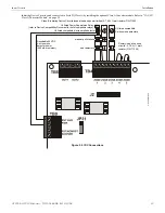
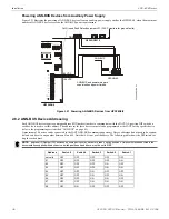
to the corresponding A+ and A- terminals on the CAC-5X module. For FCC compliance with Class A wiring, a ferrite bead (supplied
with the CAC-5X board) is required for NAC 1 and for NAC 2. If using NAC 1 and/or NAC 2 with Class A wiring, a ferrite must be
used for each NAC with wiring as shown in Figure 2.15.
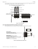
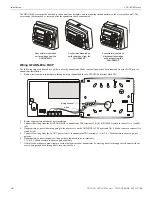
2.7.2 4XTMF Option Module
The 4XTMF module can be plugged into connectors J4 and J5 on the main circuit board.
The following steps must be followed when installing the 4XTMF module:
1.
Remove all power (AC and DC) from the FACP before installing the modules.
2.
Cut jumper JP30 on the main circuit board to allow the control panel to supervise the placement of the 4XTMF option module.
3.
Install the two supplied metal standoffs in the locations indicated. These standoffs provide the required earth ground protection.
4.
Carefully plug the connectors on the option module into connectors J4 and J5 on the FACP main circuit board, being careful not to
bend any pins.
5.
Secure the option module to the standoff on the main circuit board with the supplied screws.
6.
For proper 4XTM operation, the output relays must be programmed for the factory default settings: Alarm Relay 1, Trouble Relay 2
and Supervisory Relay 3.
7.
When the installation has been completed, connect the wiring to the modules as indicated in the following sections.
8.
Test system for proper operation.
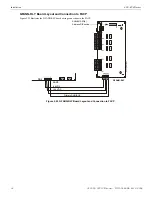
Figure 2.15 Wiring NACs and IDCs for Class A Operation
CAC-5X Class A Converter Module
GF505
Circuit Board
Class B (Style B) IDC - 4.7 K
Ω
½ watt ELR resistor
P/N:71252 (supervised and power-limited)
Dummy load all unused
circuits - 4.7 K
Ω
½ watt resistor
(P/N: 71245)
Polarized
Bell
Circuit polarities
shown in alarm
condition
Class A (Style Z) NAC
(supervised and power-limited)
Class A (Style D) IDC
(supervised and power-limited)
Polarized
Strobe
Polarized
Horn
Smoke
Smoke
Pull Station
Pull Station
Heat
Heat
m
s10
ud
cl
assa
.w
mf
B+ B- B+ B-
A+ A- A+ A-
A+ A- A+ A- A+ A- A+ A- A+ A-
B+ B- B+ B- B+ B- B+ B- B+
Ferrite Bead
p/n 50116546-001
30
GF505 & GF510 Manual —
P/N
53164
:B5 6/12/2018