5
CONVERTING TO LP VAPOR
1. On 10 kW units, open the roof, loosen the forward clamp
on the air inlet hose, and slide the hose away from the hose
fitting.
2. Slide the fuel selector pin on the carburetor out towards the
back of the enclosure.
3. Replace the inlet hose and tighten the clamp securely.
4. On all other models, simply remove the air cleaner cover and
slide the fuel selector pin outward from the natural gas to the
LP position.
INSTALLING & CONNECTING GAS LINES
1. Both natural gas and LP Vapor are highly volatile substances,
so strict adherence to all safety procedures, codes, standards
and regulations is essential.
Gas line connections should be made by a certified plumber
familiar with local codes. Always use AGA-approved gas pipe
and a quality pipe sealant or joint compound.
Verify the capacity of the natural gas meter or the LP tank in
regards to providing sufficient fuel for both the generator and
other operating appliances.
2. Most applications will require an external manual shutoff valve
on the fuel line.
General Information
Summary of Contents for Generator
Page 1: ...855 GEN INFO INSTALLATION GUIDELINES Air cooled Generators ...
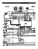
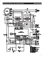
Page 19: ...17 Wiring Diagram Schematic 15kW Drawing No 0H6198 D Electrical Data ...
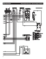
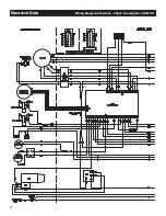
Page 20: ...18 Electrical Data Wiring Diagram Schematic 15kW Drawing No 0H6198 D ...
Page 21: ...19 Wiring Diagram Schematic 15kW Drawing No 0H6198 D Electrical Data ...
Page 22: ...20 Electrical Data Wiring Diagram Schematic 20kW Drawing No 0H7570 B ...
Page 23: ...21 Wiring Diagram Schematic 20kW Drawing No 0H7570 B Electrical Data ...
Page 24: ...22 Electrical Data Wiring Diagram Schematic 20kW Drawing No 0H7570 B ...
Page 25: ...23 Wiring Diagram Schematic 10kW Drawing No 0J2939 B Electrical Data ...
Page 26: ...24 Electrical Data Wiring Diagram Schematic 10kW Drawing No 0J2939 B ...
Page 27: ...25 Wiring Diagram Schematic 10kW Drawing No 0J2939 B Electrical Data ...


