background image

TABLE OF CONTENTS

Introduction ......................................................... Inside Front Cover
 

Read this Manual Thoroughly ..............................................IFC

 Contents 

................................................................................1


Operation and Maintenance ....................................................1


How to Obtain Service ............................................................1

Safety Rules ...................................................................................1
 Standards 

Index 

.....................................................................3

Unpacking/Inspection .....................................................................3
Before You Begin ............................................................................3
Site Preparation and Generator Placement ......................................4
Coverting to LP Vapor ....................................................................5
Installing & Connecting Gas Lines ..................................................5
Generator Activation .......................................................................6
 Activation 

Chart 

.....................................................................7

Generator Connections ...................................................................8
 Battery 

Installation..................................................................9

Appendix A - RTSX and RTSD Transfer Switch 

   Installation & Operational Testing .................................................9
 

Selected Circuit Coverage .....................................................10


Whole-house Circuit Coverage .............................................10

 Electrical 

Connections 

..........................................................11

 Operational 

Testing 

...............................................................12

Appendix B - Digital Load Managment (DLM) ................................14
Appendix C - Digital Load Managment (DLM) Modules..................15
 

Connecting Load Shed Module (LSM) Connections ...............15


Functional Tests and Adjustments .........................................16

Appendix D - Setting the Automatic Exercise Function ...................16
Electrical Data ..............................................................................17

INTRODUCTION

Thank you for purchasing this compact, high performance, air-
cooled, engine-driven generator. It is designed to automatically 
supply electrical power to operate critical loads during a utility 
power failure.

This unit is factory installed in an all-weather, metal enclosure that 

is intended exclusively for outdoor installation.

 This generator 

will operate using either vapor withdrawn liquid propane (LP) or 
natural gas (NG).

NOTE:

This generator is suitable for supplying typical 

residential loads such as Induction Motors (sump 

pumps, refrigerators, air conditioners, furnaces, etc.), 

Electronic Components (computer, monitor, TV, etc.), 

Lighting Loads and Microwaves.

READ THIS MANUAL THOROUGHLY

If any portion of this manual is not understood, contact the 
nearest Dealer for starting, operating and servicing procedures.

Throughout this publication, and on tags and decals affixed to the 
generator, DANGER, WARNING, CAUTION and NOTE blocks are 
used to alert personnel to special instructions about a particular 
operation that may be hazardous if performed incorrectly or 
carelessly. Observe them carefully. Their definitions are as follows:

INDICATES A HAZARDOUS SITUATION OR ACTION WHICH, IF 

NOT AVOIDED, WILL RESULT IN DEATH OR SERIOUS INJURY.

Indicates a hazardous situation or action which, if not 

avoided, could result in death or serious injury.

Indicates a hazardous situation or action which, if not 

avoided, could result in minor or moderate injury.

NOTE:

Notes contain additional information important to a 

procedure and will be found within the regular text 

body of this manual.

These safety warnings cannot eliminate the hazards that they 
indicate. Common sense and strict compliance with the special 
instructions while performing the action or service are essential to 
preventing accidents.

Four commonly used safety symbols accompany the 

DANGER

WARNING

 and 

CAUTION

 blocks. The type of information each 

indicates is as follows:

n

 This symbol points out important safety information that, 

if not followed, could endanger personal safety and/or 

property of others.

Table of Contents

Summary of Contents for Generator

Page 1: ...855 GEN INFO INSTALLATION GUIDELINES Air cooled Generators ...

Page 2: ...as Induction Motors sump pumps refrigerators air conditioners furnaces etc Electronic Components computer monitor TV etc Lighting Loads and Microwaves READ THIS MANUAL THOROUGHLY If any portion of this manual is not understood contact the nearest Dealer for starting operating and servicing procedures Throughout this publication and on tags and decals affixed to the generator DANGER WARNING CAUTION...

Page 3: ...se Instructions The manufacturer suggests that these rules for safe operation be copied and posted near the unit s installation site Safety should be stressed to all operators and potential operators of this equipment Study these SAFETY RULES carefully before installing operating or servicing this equipment Become familiar with this Owner s Manual and with the unit The generator can operate safely...

Page 4: ...l appropriate covers guards and barriers are in place secured and or locked before operating the generator If work must be done around an operating unit stand on an insulated dry surface to reduce shock hazard Do not handle any kind of electrical device while standing in water while barefoot or while hands or feet are wet DANGEROUS ELECTRICAL SHOCK MAY RESULT The National Electrical Code NEC requi...

Page 5: ...unpacking carefully inspect the contents for damage This standby generator set is ready for installation with a factory supplied and pre mounted base pad and has a weather protective enclosure that is intended for outdoor installation only If this generator is used to power electrical load circuits normally powered by a utility power source it is required by code to install a transfer switch The t...

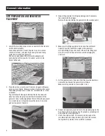
Page 6: ...rushed stone Compact and level the stone A concrete pad can be poured if desired 3 Inspect the generator for shipping damage and if necessary file a claim with the shipper Remove the bands holding the generator to the wooden pallet 4 Make sure the lifting equipment to be used has sufficient capacity to safely handle the weight of the generator Use nylon lifting straps and connect them to the lifti...

Page 7: ... LP position INSTALLING CONNECTING GAS LINES 1 Both natural gas and LP Vapor are highly volatile substances so strict adherence to all safety procedures codes standards and regulations is essential Gas line connections should be made by a certified plumber familiar with local codes Always use AGA approved gas pipe and a quality pipe sealant or joint compound Verify the capacity of the natural gas ...

Page 8: ...lator ports inside the generator to make sure there s enough pressure for proper generator operation The local gas supplier is responsible for ensuring adequate pressure so if the pressure is too low or if it s greater than 14 inches of water column contact the gas supplier 7 When finished checking the gas pressure close the manual shutoff valve GENERATOR ACTIVATION When battery power is applied t...

Page 9: ...ation code wait 3 5 seconds for the next display ENTER ACTIVATION CODE Passcode TROUBLESHOOTING Display Reads Use ARROW keys to scroll and find the first number of your Activation Code Press ENTER to select Repeat this step until all digits have been entered Use ESCAPE to correct previous digits Display Reads Activation is complete when all digits are entered above and your screen shows this displ...

Page 10: ...wer leads to the circuit breaker 6 Now connect the red and black power leads to the circuit breaker Since this is a single phase application it doesn t matter which wire is connected to which lug 7 Connect the green equipment ground wire to the ground bus bar and torque to 35 inch lbs The torque values are 10 14 AWG 35 in lbs 8 AWG 40 in lbs 4 6 AWG 45 in lbs T1 N2 N1 209 210 0 194 23 NEUT G N D 8...

Page 11: ...asing a battery for the generator refer to the Owner s Manual for the recommended battery Group 26R 12 Volt 525cca minimum 2 Follow all of the procedures and safety precautions in the generator Owner s Manual when installing the battery Verify the switch is in the off position When preparing for operational testing DO NOT connect the battery until transfer switch connections are complete APPENDIX ...

Page 12: ...1 The generator powers only designated circuits that are grouped together and wired into a separate priority distribution panel The transfer switch is installed between the main distribution panel and the priority panel The amperage rating of the transfer switch must be equal to or greater than the highest amperage rating of the utility and generator breakers feeding the switch WHOLE HOUSE CIRCUIT...

Page 13: ...utility to the appropriate lugs in the transfer switch The lugs are clearly marked in the switch N Normal Utility Supply E Generator Connection Panel T Load Distribution Panel 2 Neutral wires from both the utility and the generator are connected to the same neutral lug in the switch 3 Connect the control wires from the generator to the designated locations Wires 0 23 and 194 connect to the termina...

Page 14: ...minations Repeat the same voltage checks on terminals T1 and T2 to make sure current is flowing properly through the contactor 4 Switch the generator s main circuit breaker OFF and put the mode switch in the OFF position 5 Make sure utility power is OFF and place all of the individual circuit breakers in the main distribution panel in the OFF position 6 Locate the transfer handle insert the metal ...

Page 15: ...still OFF use the transfer handle to move the main contacts to the UP utility position 11 Close the main breaker to turn utility power ON 12 Switch the generator s main breaker to the ON position and put the mode switch in AUTO 13 Shut OFF utility power and make sure the generator starts automatically after the line interrupt delay 14 Switch the utility breaker to ON and make sure that power is au...

Page 16: ...off 19 Shut OFF utility power again The generator should start and the entire priority load should transfer to the generator 20 Close the main breaker to restore utility power and allow the engine to cool down and shut itself off Operational tests are now complete Refer to Appendix E Setting the Automatic Exercise Function to complete the installation APPENDIX B DIGITAL LOAD MANAGEMENT DLM 1 To co...

Page 17: ...n and the sequence repeats However the level that caused the overload and all levels higher will not be enabled again for 30 minutes Control of Air Conditioner Load 1 Route the thermostat cable from the furnace thermostat to the outdoor air conditioner unit to the transfer switch 2 Connect the wire to the terminal strip terminals Air 1 on the LSM as shown in Figure 2 2 These are normally closed co...

Page 18: ...NG NEUTRAL AND ENCLOSURE NEUTRAL BONDED DISCONNECT BUSBAR BETWEEN 600 Volt 5 amp type and rating Replace with UL listed fuse of same 0D3587 0G4220 0G9651A CONNECTIONS SOURCE UTILITY N1 N2 UPPER LOWER 0 GROUND 15B 12V 23TRANSFER AIR 1 AIR 2 PRIORITY 1 PRIORITY 2 PRIORITY 3 PRIORITY 4 T1 NEUTRAL CONTACTOR 1 CONTACTOR 2 CONTACTOR 3 CONTACTOR 4 WARNING CUSTOMER CONNECTION NOTE WIRE ORIENTATION 0G8137 ...

Page 19: ...17 Wiring Diagram Schematic 15kW Drawing No 0H6198 D Electrical Data ...

Page 20: ...18 Electrical Data Wiring Diagram Schematic 15kW Drawing No 0H6198 D ...

Page 21: ...19 Wiring Diagram Schematic 15kW Drawing No 0H6198 D Electrical Data ...

Page 22: ...20 Electrical Data Wiring Diagram Schematic 20kW Drawing No 0H7570 B ...

Page 23: ...21 Wiring Diagram Schematic 20kW Drawing No 0H7570 B Electrical Data ...

Page 24: ...22 Electrical Data Wiring Diagram Schematic 20kW Drawing No 0H7570 B ...

Page 25: ...23 Wiring Diagram Schematic 10kW Drawing No 0J2939 B Electrical Data ...

Page 26: ...24 Electrical Data Wiring Diagram Schematic 10kW Drawing No 0J2939 B ...

Page 27: ...25 Wiring Diagram Schematic 10kW Drawing No 0J2939 B Electrical Data ...

Page 28: ...Power Systems S45 W29290 Hwy 59 Waukesha WI 53187 1 855 GEN INFO honeywellgenerators com The Honeywell Trademark is used under license from Honeywell International Inc Honeywell International Inc makes no representation or warranties with respect to this product ...

Reviews: