


6
3. Where the gas line is to enter the generator, install a T-fitting to
allow for gas pressure monitoring. In some cases a sediment
trap may also be installed.
4. When connecting the gas line to the generator, use the
provided section of UL Listed or AGA-approved flexible fuel
line in accordance with local regulations. The purpose of the
flexible fuel line is to ensure that vibration from the generator
does not cause a gas leak at one of the connection points, so
it’s important that the line be installed with as few bends as
possible.
5. Never bend the flexible fuel line to avoid using an elbow.
Bending the flexible line decreases its ability to absorb
vibrations and defeats its purpose as well as constricts the
actual fuel flow.
6. After checking for leaks, check the gas pressure at the
regulator ports inside the generator to make sure there’s
enough pressure for proper generator operation.
The local gas supplier is responsible for ensuring adequate
pressure, so if the pressure is too low, or if it’s greater than
14 inches of water column, contact the gas supplier.
7. When finished checking the gas pressure, close the manual
shutoff valve.
GENERATOR ACTIVATION
When battery power is applied to the generator during the
installation process, the controller will light up. However, the
generator still needs to be activated before it will automatically run
in the event of a power outage.
Activating the generator is a simple one time process that is
guided by the controller screen prompts. Once the product is
activated, the controller screen will not prompt you again, even if
you disconnect the generator battery.
After obtaining your activation code, please complete the following
steps at the generator’s control panel in the
Activation Chart
(shown on the following page).
General Information
Summary of Contents for Generator
Page 1: ...855 GEN INFO INSTALLATION GUIDELINES Air cooled Generators ...
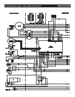
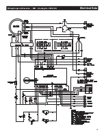
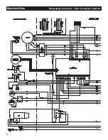
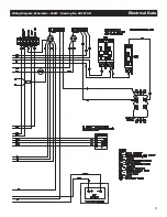
Page 19: ...17 Wiring Diagram Schematic 15kW Drawing No 0H6198 D Electrical Data ...
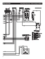
Page 20: ...18 Electrical Data Wiring Diagram Schematic 15kW Drawing No 0H6198 D ...
Page 21: ...19 Wiring Diagram Schematic 15kW Drawing No 0H6198 D Electrical Data ...
Page 22: ...20 Electrical Data Wiring Diagram Schematic 20kW Drawing No 0H7570 B ...
Page 23: ...21 Wiring Diagram Schematic 20kW Drawing No 0H7570 B Electrical Data ...
Page 24: ...22 Electrical Data Wiring Diagram Schematic 20kW Drawing No 0H7570 B ...
Page 25: ...23 Wiring Diagram Schematic 10kW Drawing No 0J2939 B Electrical Data ...
Page 26: ...24 Electrical Data Wiring Diagram Schematic 10kW Drawing No 0J2939 B ...
Page 27: ...25 Wiring Diagram Schematic 10kW Drawing No 0J2939 B Electrical Data ...