background image

10 

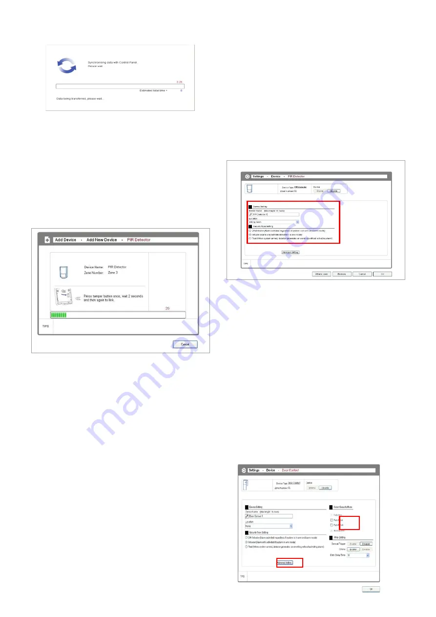
2. The software will issue a request to the Control 
Panel to go into code learning mode. 


3. Press the learn/tamper button on the selected PIR 
detector within 30 seconds to transmit a code to be 
picked up by the Control Panel. 

 
Note: See the screen prompt (also the figure below) 
to find out the  location of the  learn/tamper button 
on the device.  After you press the learn/tamper 
button, the Control Panel will also beep to indicate 
the reception of the learning code. 


4. Once the system has learnt the device’s code, the 

device setting window will appear up for you to 

configure the device’s name, location, and security 

type: 


Name:

 Specify a name for easy identification. 

Location:

 Specify where the device is installed. 

Security Type:

 Specify the level of alarm when the 

device is triggered. 

 
5. After adding/replacing a security device (PIR or 
door/window contact detector) to the system, refit the 
detector in position to its battery cover before exiting 
the add device screen. This is will prevent the tamper 
alarm from initiating if the tamper button is press and 
release during final installation of a detector. 
 

IMPORTANT: Specify the Location of device 
carefully as it affects many aspects in the system: 
1) If one or more IP cameras are installed in your 
system, then when a PIR or other type of detector 

is triggered, the camera assigned to the SAME 
location will start recording. Therefore you should 
plan beforehand and assign the location group 
carefully. 
2) When the device is triggered, the Web software 
and the smartphone app will also inform the user 
of the location. So the correct setting of location is 
critical for the information. 
3) After a security detector such as a wireless PIR 
or door contact detector has been added, the 
device number is the “Zone Number” (1-36) 
displayed at the top of the window. The zone 
number for each security device is stored in the 
Control Panel   


Part-ArmI/II setup of a security device 


All PIR movement and door/window contact security 
detectors can be also setup to operate with Part-Arm I 
or Part-Arm II security modes. 
 
If a group of detectors have been set so that they can 
activate in Part-Arm I, this means that when the Control 
Panel is armed in Part-Arm I mode, then only those 
detectors setup will become active. An example would 
be part-arming the ground floor of your home while you 
are gone to sleep so you can move around upstairs at 
night without initiating an alarm 


Part arm setup of a device can be done during the 
adding process or after the device has been added 
in “Settings – Devices”. 


Summary of Contents for Friedland GlobalGuard

Page 1: ...1 GlobalGuard Alarm System Software Operating Manual ...

Page 2: ...new Programme 13 2 6 1 2 Maintaining Programme 13 2 6 2 Event 14 2 6 2 1 Adding New Event 14 2 6 2 2 Maintaining Event 14 2 6 3 Schedule 17 2 6 3 1 Adding New Schedule 17 2 6 3 2 Mainitaining Schedule 17 2 6 4 Device 19 2 6 5 System 20 2 6 5 1 User 20 2 6 5 2 Siren 20 2 6 5 3 Time and date setup 21 2 6 5 4 Control Panel 21 2 6 5 5 Friedland Spectra 21 Lighting Controller Optional 3 Exiting the sof...

Page 3: ...dland co uk is used to do the following when your PC is connected to the internet and you have created an online account control the security functions i e arm disarm and check status activate home automation programmes view playback up to 8 CCTV cameras when optional camera s added to system setup accounts and email contacts 6 Mobile devices compatible with the GlobalGuard remote access App Apple...

Page 4: ...ftware or the mobile App By doing so will prevent yourself or other home users from remotely viewing controlling the security home automation functions from the online web software or App If the PC software is loading or running then the 2 nd RF wireless communication to Control Panel LED on the IP gateway will turn orange colour and will prevent the system feeding back the current system status i...

Page 5: ...Do not configure the Control Panel using its keypad while the GlobalGuard software is still running as this may result in data inconsistency 2 With the exception of actions such as Add Device Replace Device Remove Device in order for other settings to take effect the Sync function must be used to apply the new settings to the Control Panel When you double click the GlobalGuard desktop icon the sys...

Page 6: ...ice to access a window see below that contains specific information about the device such as Device Name Device Type Number Location and so forth Examples When you click the system will display this message window When you click the system will display this message window CUSTOMER HELPLINE Most issues can be solved over the phone in a few minutes Please contact our Helpline Team on the number belo...

Page 7: ...rogramme Keys 1 Click Home Page in the Top Menu 2 Click on the Living1 icon or any other available programme that may have been created as described later in this manual 3 The system will display a small function menu above the icon and you can specify the location of the programme key In this example I has been chosen and this means Programme Key I has been redefined to Living1 4 After you have r...

Page 8: ...this operation immediately after each settings change to ensure the data in the Control Panel is always up to date The Sync window see below will appear whenever the system is writing data back to the Control Panel indicating that the system is in the process of synchronizing Important note during Syncing When data is being synced to the Control Panel any security functions and home automation Pro...

Page 9: ... entry exit delay It is recommended to install the 1 st detector zone1 you add at the entry exit point of your property The entry delay period for a security device can be setup in Advance Settings of that device The exit delay can be setup in Settings Device Control Panel page 2 5 1 Add New Device On the interface screen you can find two buttons on the left side Add New Device and Replace Device ...

Page 10: ...fects many aspects in the system 1 If one or more IP cameras are installed in your system then when a PIR or other type of detector is triggered the camera assigned to the SAME location will start recording Therefore you should plan beforehand and assign the location group carefully 2 When the device is triggered the Web software and the smartphone app will also inform the user of the location So ...

Page 11: ...the device setting window for you to configure the device s properties 2 5 2 Replace Device When you click the Replace Device on the left side all existing devices will be displayed on the right panel To replace a device simply click on an icon and follow the screen prompts to complete the procedures This function is useful whenever a device has become faulty You can simply purchase the same devic...

Page 12: ...e home page of the PC setup software or via the online remote access software Events An Event is a set of multiple actions that take place when the system is triggered by a detector For example an Event can be created to automatically turn on the porch lamp connected to a ON OFF device when the door window contact detector detects the front door opening Unlike Programmes Events are activated by de...

Page 13: ...e sound effect playback by the Control Panel you can choose None or Chime sound Programme Shows the status of the selected Programme click Enable to activate the Programme and Disable to deactivate it Step1 Configure the type of security mode for the Control Panel to employ 1 No Setting Use the current security mode set for the Control Panel without making any change 2 Fully Arm the Control Panel ...

Page 14: ...Event Name you may create a name for the selected Event for easy identification Number Denotes the number of Events currently available on the system you can have up to a maximum of 32 Events Step1 Specify trigger method Device Triggered or System Triggered 1 Setting an Event to be Device Triggered 1 Device Trigger You can specify the device i e Zone Detector Device Keypad Remote that the system h...

Page 15: ... e 08 00 22 00 Example System Trigger Step2 Specify the action to be taken when the trigger has been set off You can configure the system to take one of the following two actions 1 Control Device the system will take whatever action s you have configured for Control Device including Sound You can configure up to 16 actions 2 Programmes the system will execute the selected Programme Example Configu...

Page 16: ...d that System Trigger has been made unavailable This means that the Programme that was selected previously involve the change of the Control Panel security modes Step3 Specify the duration of delay time for Action 2 to be executed Optional Example Setting the delay time to 5 seconds before Action 2 is executed Step4 Activate Action 2 Optional The steps and rules for Action 2 are identical to what ...

Page 17: ... relevant Event maintenance information Name Schedule Name you may create a name for the selected Schedule for easy identification Number Denotes the number of Schedules currently available on the system you can have up to a maximum of 16 Events Step1 Specify trigger mode Fixed Time and Weekly 1 Setting a Schedule to be triggered at Fixed Time 1 1 Set Action Time Specify the time for the Schedule ...

Page 18: ...Control Panel s security mode Step3 Specify the duration of delay time for Action 2 to be executed Optional Example Setting the delay time to 1 minute before Action 2 is executed Step4 Activate Action 2 Optional The steps and rules for Action 2 are identical to what have been covered for Action 1 Refer to the descriptions for Action 1 if needed If you wish to simplify the configuration process sim...

Page 19: ...l be removed as well including Programmes Events Schedules If you have to purchase a new device to replace a faulty one it is recommended that you use the Add Device Replace Device for the replacement If you remove the device and add it again you will have to reconfigure all relevant settings that you have previously made before Different device types would have different advanced settings Example...

Page 20: ...ical PIN codes shared by two or more users will not be accepted 3 PIN codes must 4 digits in length 4 When a user does not have a valid PIN code or a remote they will be shown as Disable on the list to the left If a user is in possession of a remote a remote control icon will appear next to the user in the edit window 2 6 5 2 Siren You can configure relevant Siren settings here For instruction on ...

Reviews: