


ENS7003R16 KO65 2013
7
REMOVE THE RELAY MODULE FROM ITS
SUB BASE AND FIX THE SUB BASE
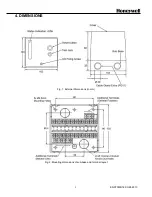
1. Loosen the M3 fixing screw as shown in Fig. 1 by
about eight turns using a Philips head screwdriver.
2. Take the subbase and cover with both hands and
unfold them gently. Fold the relay module
upwards, the turning point is on the top. Do not
apply excessive force, otherwise damage may
occur.
3. Punch out the needed conduit knockout holes for
the wiring as shown in Figs 1 and 2, and install the
wiring conduit(s).
4. Using the fixing screws, mount the subbase in the
specified position.
Avoid to overtighten the fixation screw on the
front of the device, to avoid damaging the
(Phillips) head of the screw.
WIRING THE RELAY MODULE BOTTOM
TERMINALS
1. For applications with a UV detector, remove the
jumper terminal located at the terminal block on
the bottom of the relay module.
2. For applications using remote communication,
connect communication cable to “BUS” terminal
located at the terminal block on the bottom of the
relay module. In addition, set the communication
address uring the rotary switches at the bottom of
the relay module.
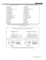
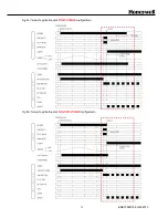
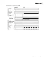
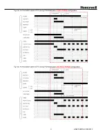
WIRING THE SUB BASE
1. Fig. 2 shows the layout of the terminals on the
subbase, and Figs. 3-1 to 3-3 show examples of
connections to external equipment. Regarding the
wiring to the flame detector, refer to Fig. 4.
2. When using Intermittent Pilot, connect the pilot
valve to Terminal 5. Connect the main valves to
Terminal 7 (Enhanced and Ultimate models:
connect main valve 1 to Terminal 7 and main valve
2 to Terminal 12 for the VPS function)
3. When using Interrupted Pilot, connect the pilot
valve to Terminal 6. Connect the main valves to
Terminal 7 (Enhanced and Ultimate models:
connect main valve 1 to Terminal 7 and main valve
2 to Terminal 12 for the VPS function)
4. When using direct ignition (DBI), jumper Terminals
15 and 22. And connect the Main(DBI) valves to
Terminal 5.
5. When not using purge position interlock, jumper
Terminals 15 and 16.
6. When not using start position interlock, jumper
Terminals 13 and 17.
7. When not purge and start position interlocks,
jumper Terminals 15 and 16 as well as Terminals
13 and 17 simultaneously.
8. Connect the safety switch circuit (lockout
interlocks) between Terminals 15 and 18. The
safety switch circuit must be closed always,
otherwise a lockout occurs immediately.
9. For non-floating mains power grids (Neutral to
Ground), connect the Line-L to Terminal 1 and the
Line-N to Terminal 2. Use a correct fuse: 10A fast
blow maximum.
10. Check all wiring circuits and assure that the
correct fuse is installed. Check the correct voltage.
11. Finally plug the relay module on to its sub base
and fix it with the M3 fixing screw. Do not overtight
the screw.
12. When using a surge absorber, connect it between
Terminal 2 and application ground.
13. Connect the mains supply voltage using 0.75mm
2
or larger lead wire.
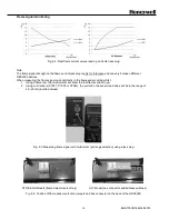
14. Never connect blank stripped wires to the wiring
sub base. Loose wire strands may cause short
circuits to electrically safe contacts which may
cause an electrical shock hazard.
Always use cable lugs to attach the wires to the
sub base.
See Fig 2-1 for do’s and don’ts about wiring.
Fig. 2-1: Wiring the sub base terminals
Summary of Contents for DBC2000E10 Series
Page 13: ...ENS7003R16 KO65 2013 13 ...
Page 15: ...ENS7003R16 KO65 2013 15 ...
Page 16: ...ENS7003R16 KO65 2013 16 ...
Page 17: ...ENS7003R16 KO65 2013 17 ...
Page 18: ...ENS7003R16 KO65 2013 18 ...
Page 19: ...ENS7003R16 KO65 2013 19 ...
Page 20: ...ENS7003R16 KO65 2013 20 ...
Page 21: ...ENS7003R16 KO65 2013 21 ...
Page 27: ...ENS7003R16 KO65 2013 27 ...
Page 28: ...ENS7003R16 KO65 2013 28 ...
Page 29: ...ENS7003R16 KO65 2013 29 ...
Page 30: ...ENS7003R16 KO65 2013 30 ...
Page 31: ...ENS7003R16 KO65 2013 31 ...
Page 32: ...ENS7003R16 KO65 2013 32 ...
Page 33: ...ENS7003R16 KO65 2013 33 ...
Page 34: ...ENS7003R16 KO65 2013 34 ...