


ENS7003R16 KO65 2013
10
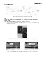
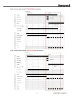
Flame signal monitoring
Fig. 4-2: Real flame current versus reading on frontal jack plug.
Note:
The flame signal strength on the flame current jack plug is only for reference and can vary between different
DBC2000 devices.
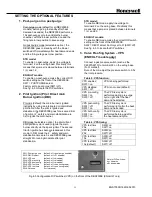
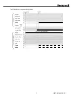
When measuring the flame signal current directly in the flame sensor wiring whilst:
1. Using a flame rod, the (multi-)meter will show the real flame current in µA.
2. Using a UV sensor (C7027, C7035 or C7044), the current in the sensor lead wires will be in the range of
20…25mA (inverted values).
Fig. 4-3: Measuring flame signal with multi meter (µA range selection) using a jack plug.
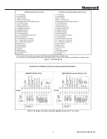
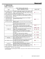
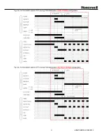
STD & ENH Models (flame detector select only)
ULT Model (bus connector and address switches)
Fig. 4-4: Position of flame sensor selection jumpers and bus connector on the back of the DBC2000.
Summary of Contents for DBC2000E10 Series
Page 13: ...ENS7003R16 KO65 2013 13 ...
Page 15: ...ENS7003R16 KO65 2013 15 ...
Page 16: ...ENS7003R16 KO65 2013 16 ...
Page 17: ...ENS7003R16 KO65 2013 17 ...
Page 18: ...ENS7003R16 KO65 2013 18 ...
Page 19: ...ENS7003R16 KO65 2013 19 ...
Page 20: ...ENS7003R16 KO65 2013 20 ...
Page 21: ...ENS7003R16 KO65 2013 21 ...
Page 27: ...ENS7003R16 KO65 2013 27 ...
Page 28: ...ENS7003R16 KO65 2013 28 ...
Page 29: ...ENS7003R16 KO65 2013 29 ...
Page 30: ...ENS7003R16 KO65 2013 30 ...
Page 31: ...ENS7003R16 KO65 2013 31 ...
Page 32: ...ENS7003R16 KO65 2013 32 ...
Page 33: ...ENS7003R16 KO65 2013 33 ...
Page 34: ...ENS7003R16 KO65 2013 34 ...